Wiring Diagram For Mrcool Diy Wiring Diagram Pictures

Diy Wiring Schematics Follow wiring diagrams included with your kit; connect wires from both units according to color codes (usually black, white, green). secure connections with wire nuts or connectors as recommended. step 7: final checks. before powering up: double check all connections—both refrigerant lines and electrical wires—to ensure they are secure. Scenario 1: default 2 wire communication setup. standard setup (all systems): for most mrcool versa pro systems, the default wiring setup utilizes a two wire communication system between the thermostat and the air handler. this is true for systems from 18,000 to 60,000 btu (18k to 60k). exceptions for 18k 30k systems: while the standard wiring.

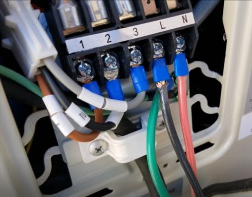
Mrcool 36k Wiring Diagram Mrcool diy installation guides & product manuals downloadable & user friendly – mrcool diy direct. email us (417) 291 9921 toll free (800) 651 9297. mrcool diy installation guides & product manuals .pdf downloads. lori from georgetown, united states has recently purchased 1.8 lb r410a refrigerant refill kit with gauge.an hour ago. This guide provides a breakdown for 1.5 2.5 ton models (mvp 18, 24, 30) and 3 5 ton models (mvp 36, 48, 60), ensuring that your setup runs smoothly. for these models, the wiring setup between the condenser and the air handler is similar to that of a mini split system. a 14 4 communication wire is used, connecting terminals 1, 2, and 3 on both. Step 1 inside. locate the cardboard wall template. place the template on the wall at the installation location. use the template to mark the location of the drill points for the mounting screws and wall hole. make sure that the drill points for the mounting screws are located on wall studs. remove the template. Use wire cutters to cut off the wire end and then peel away about 1 in (25 mm) of the insulation layer. use a screwdriver to unscrew the terminal screw on the terminal board. use needle nose pliers to bend the solid wire into a ring that fits the terminal screw. form a proper ring and attach to the terminal board.

Wiring Diagram For Mrcool Diy Wiring Diagram Pictures Step 1 inside. locate the cardboard wall template. place the template on the wall at the installation location. use the template to mark the location of the drill points for the mounting screws and wall hole. make sure that the drill points for the mounting screws are located on wall studs. remove the template. Use wire cutters to cut off the wire end and then peel away about 1 in (25 mm) of the insulation layer. use a screwdriver to unscrew the terminal screw on the terminal board. use needle nose pliers to bend the solid wire into a ring that fits the terminal screw. form a proper ring and attach to the terminal board. This guide provides a comprehensive step by step process to help you install your system with confidence. assessing your space: measure the area you want to cool to ensure the 18k btu unit is adequate. consider room size, ceiling height, and sunlight exposure. gather necessary tools such as a drill, level, screwdrivers, and materials including. All wiring must be performed in accordance with the wiring diagrams shown in fig. 7.1 and demonstrated in the images shown here. mrcool page 31 page 33 example indoor unit: t3.15al 250vac, t5al 250vac, t3.15a 250vac, t5a 250vac, etc. example outdoor unit: all wiring must be performed strictly in accordance with the wiring t20a 250vac.

Wiring Diagram For Mrcool Diy This guide provides a comprehensive step by step process to help you install your system with confidence. assessing your space: measure the area you want to cool to ensure the 18k btu unit is adequate. consider room size, ceiling height, and sunlight exposure. gather necessary tools such as a drill, level, screwdrivers, and materials including. All wiring must be performed in accordance with the wiring diagrams shown in fig. 7.1 and demonstrated in the images shown here. mrcool page 31 page 33 example indoor unit: t3.15al 250vac, t5al 250vac, t3.15a 250vac, t5a 250vac, etc. example outdoor unit: all wiring must be performed strictly in accordance with the wiring t20a 250vac.

Wiring Diagram For Mrcool Diy

Mr Cool Wiring Instructions

Comments are closed.