Wiring 5 Pin Relay

5 Pin Relay Wiring Diagram Use Of Relay When wiring a 5 pin relay, it is important to understand the differences between 4 pin and 5 pin relays. a 4 pin relay will typically have two contacts in the same position as the 5 pin relay, but won’t have an additional contact point for controlling a device. 1. gather the necessary materials. before you begin the wiring process, make sure you have all the necessary materials. this includes the five pin relay, the wiring harness, wires of the appropriate size, a wire stripper, and electrical tape. having everything ready will make the process smoother and more efficient.

How Does A 5 Pin Relay Work The two most common ways to wire a 5 pin relay is with a positive trig **parts list in description below**5 pin relay wiring can be done many different ways. the two most common ways to wire a. A 5 pin relay is an electrical device that acts as a switch to control the flow of current in a circuit. it is commonly used in automotive applications to control various electrical components such as lights, fans, and motors. understanding the wiring diagram for a 5 pin relay is essential for proper installation and operation. When the relay is energized, the connection between pins 30 and 87a is opened, interrupting the current flow to the load. to wire a 5 pin relay, start by connecting pin 30 to the power source and pin 85 to the ground. then, connect pin 86 to the switch or control unit, and pin 87 to the load. The 5 pin relay is a commonly used component in electrical systems and circuits. it is designed to control the flow of electrical current and is widely used in automotive, industrial, and home applications. understanding the functionality and wiring diagram of a 5 pin relay is essential for troubleshooting and repairing electrical systems.

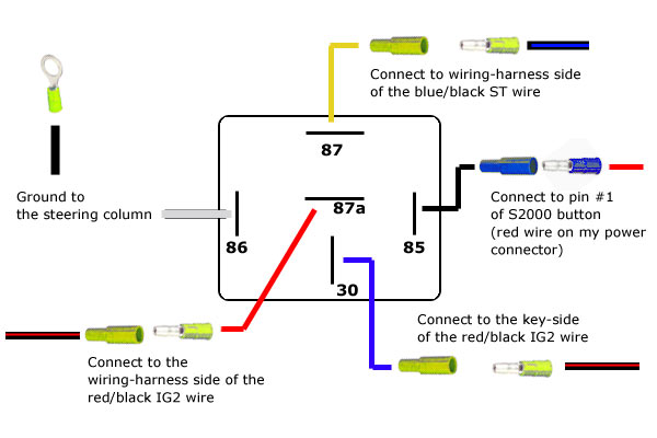
Wiring 5 Pin Relay When the relay is energized, the connection between pins 30 and 87a is opened, interrupting the current flow to the load. to wire a 5 pin relay, start by connecting pin 30 to the power source and pin 85 to the ground. then, connect pin 86 to the switch or control unit, and pin 87 to the load. The 5 pin relay is a commonly used component in electrical systems and circuits. it is designed to control the flow of electrical current and is widely used in automotive, industrial, and home applications. understanding the functionality and wiring diagram of a 5 pin relay is essential for troubleshooting and repairing electrical systems. Learn how to wire a 5 pin relay in your car, truck or powersports vehicle. in this video i go over the basics of a 5 pin spdt automotive relay using a wiring. A 5 post relay wiring diagram is a diagram that shows the proper wiring connections for a 5 pin relay. it provides a visual representation of how the relay should be wired, including the input and output connections.
Simple 5 Pin Relay Diagram Dsmtuners Learn how to wire a 5 pin relay in your car, truck or powersports vehicle. in this video i go over the basics of a 5 pin spdt automotive relay using a wiring. A 5 post relay wiring diagram is a diagram that shows the proper wiring connections for a 5 pin relay. it provides a visual representation of how the relay should be wired, including the input and output connections.

Comments are closed.