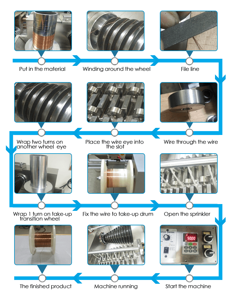
Wire Drawing Machine Wiring Diagram And Schematics

Wire Drawing Machine Wiring Diagram And Schematics Side by side comparison of the wiring diagram (drawing), the actual device, and the circuit schematic of the output circuits (mosfet and zener diode visible). image used courtesy of the author . many devices exist in both diagrams and schematics. both will contain indicators, relays, power supply connections, transformers, fuses, and others. Try smartdraw's wiring diagram software free. discover why smartdraw is the ideal wiring diagram software. make your wiring diagram. create wiring diagrams, house wiring diagrams, electrical wiring diagrams, schematics, and more with smartdraw. templates and symbols included.

Wire Drawing Machine Process Wiring Diagram And Schematics List of the best wiring diagram software. 1. edrawmax. edrawmax is a professional drawing tool that can be used to create 210 types of diagrams, including flowcharts, mind maps, org charts, uml diagrams, network diagrams, floor plans, and more. An electrical schematic is a diagram that shows how all of the wires and components in an electronic circuit are connected. they’re like a map for building or troubleshooting circuits, and can tell you almost everything you need to know to understand how a circuit works. the ability to read electrical schematics is a really useful skill to. An electrical wiring diagram could be a single page schematic of how a ceiling fan should be connected to the power source and its remote switches. a wiring diagram may include the wirings of a vehicle. for example, how the horns are powered and connected to the controller on your steering wheel. or an electrical wiring diagram can be a 200. Sometimes, to make schematics more legible, we'll give a net a name and label it, rather than routing a wire all over the schematic. nets with the same name are assumed to be connected, even though there isn't a visible wire connecting them. names can either be written directly on top of the net, or they can be "tags", hanging off the wire.

Wire Drawing Machine Process Wiring Diagram And Schematics An electrical wiring diagram could be a single page schematic of how a ceiling fan should be connected to the power source and its remote switches. a wiring diagram may include the wirings of a vehicle. for example, how the horns are powered and connected to the controller on your steering wheel. or an electrical wiring diagram can be a 200. Sometimes, to make schematics more legible, we'll give a net a name and label it, rather than routing a wire all over the schematic. nets with the same name are assumed to be connected, even though there isn't a visible wire connecting them. names can either be written directly on top of the net, or they can be "tags", hanging off the wire. Step 2: recognize major components. before you dive into the wires and connections, take a high level view of the major components included in the system. identify transformers, motors, solenoid valves, motor starters, lighting ballasts, microprocessors, switches, and other significant components by their symbols. Register for free. step 2. create your project and upload the floor plan. step 3. set the scale and select the rooms. step 4. place the devices (uplan wizard does that for you in a blink of an eye) step 5. download the offer and documentation with wiring in a single pdf.

Comments are closed.