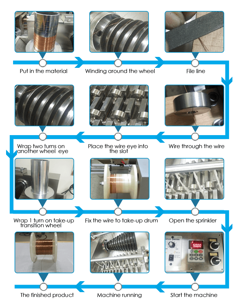
Wire Drawing Machine Process Wiring Diagram And Schematics

Wire Drawing Machine Process Wiring Diagram And Schematics Side by side comparison of the wiring diagram (drawing), the actual device, and the circuit schematic of the output circuits (mosfet and zener diode visible). image used courtesy of the author . many devices exist in both diagrams and schematics. both will contain indicators, relays, power supply connections, transformers, fuses, and others. Example of diagram reading. now let’s go back to industrial diagrams, primarily focusing on schematic diagrams.a site electrician, for each system and distribution cabinet, has a set of plans in a3 and or a4 format with ‘n’ sheets representing the installation “sequential” in control (or command) diagram and power diagram form.

Wire Drawing Machine Wiring Diagram And Schematics An electrical wiring diagram could be a single page schematic of how a ceiling fan should be connected to the power source and its remote switches. a wiring diagram may include the wirings of a vehicle. for example, how the horns are powered and connected to the controller on your steering wheel. or an electrical wiring diagram can be a 200. Step 2: recognize major components. before you dive into the wires and connections, take a high level view of the major components included in the system. identify transformers, motors, solenoid valves, motor starters, lighting ballasts, microprocessors, switches, and other significant components by their symbols. 2. wiring diagrams. a wiring diagram is a simple visual representation of an electrical system’s or circuit’s physical connections and layout. it illustrates how electrical wires are connected and where components are actually connected to the system. what are the main differences between wiring diagrams & schematic diagrams. while wiring. How to draw electrical diagrams. making wiring or electrical diagrams is easy with the proper templates and symbols: start with a collection of electrical symbols appropriate for your diagram. draw circuits represented by lines. drag and drop symbols to the circuits and connect them. use line hops if any lines need to cross.

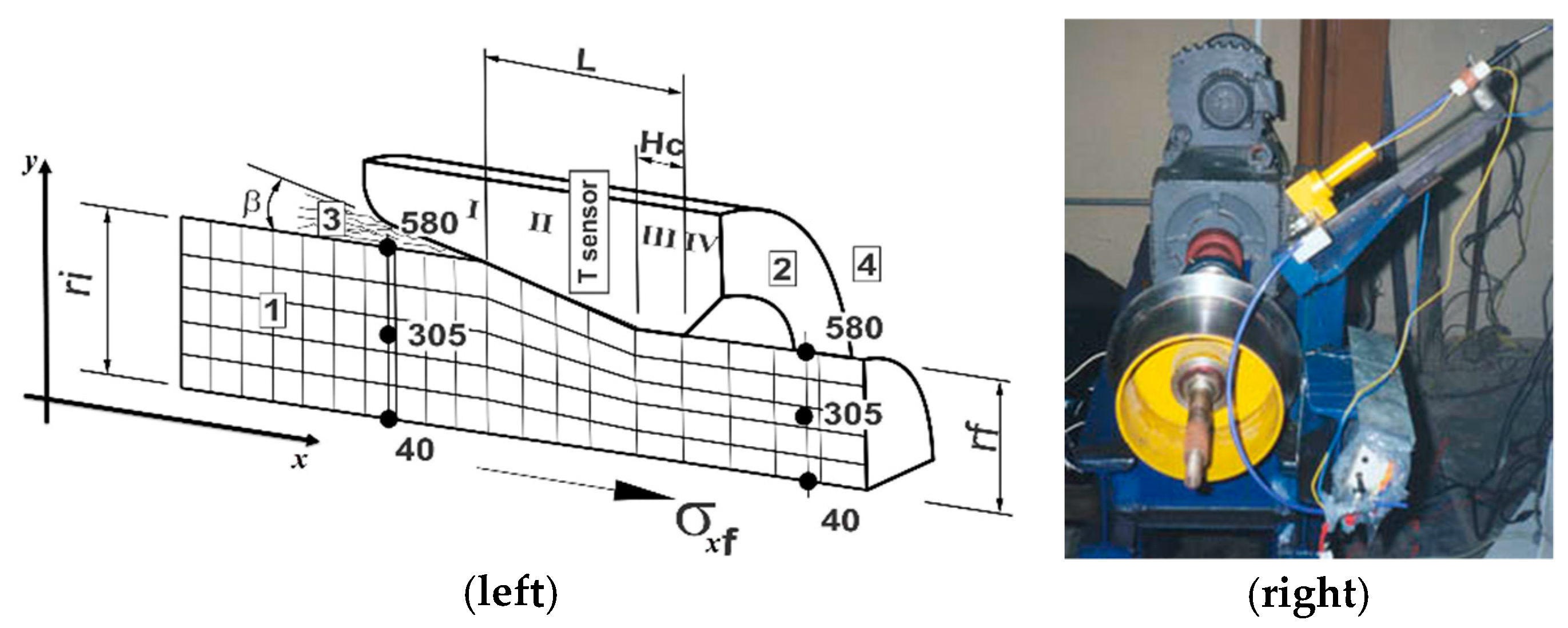
Schematic Of The Wire Drawing Process And Terminology Used In This 2. wiring diagrams. a wiring diagram is a simple visual representation of an electrical system’s or circuit’s physical connections and layout. it illustrates how electrical wires are connected and where components are actually connected to the system. what are the main differences between wiring diagrams & schematic diagrams. while wiring. How to draw electrical diagrams. making wiring or electrical diagrams is easy with the proper templates and symbols: start with a collection of electrical symbols appropriate for your diagram. draw circuits represented by lines. drag and drop symbols to the circuits and connect them. use line hops if any lines need to cross. Wiring schematics symbols are a crucial tool for electrical engineers and technicians. these symbols represent various electrical components, such as resistors, capacitors, and switches, and help professionals create accurate and detailed wiring diagrams. by using standardized symbols, engineers can easily communicate and understand complex. The two most commonly used power supply symbols are a circle with a plus sign ( ) and a circle with a minus sign ( ). the plus and minus signs indicate positive and negative terminals, respectively. 2. conductors and wires symbols. conductors and wires are represented by different symbols in wiring diagrams.

Wire Drawing Machine Process Wiring Diagram And Schematics Wiring schematics symbols are a crucial tool for electrical engineers and technicians. these symbols represent various electrical components, such as resistors, capacitors, and switches, and help professionals create accurate and detailed wiring diagrams. by using standardized symbols, engineers can easily communicate and understand complex. The two most commonly used power supply symbols are a circle with a plus sign ( ) and a circle with a minus sign ( ). the plus and minus signs indicate positive and negative terminals, respectively. 2. conductors and wires symbols. conductors and wires are represented by different symbols in wiring diagrams.

Wire Drawing

Comments are closed.