Welding Symbols With Figures Paktechpoint

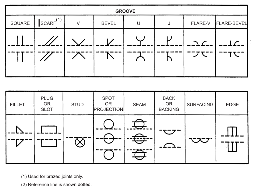
Welding Symbols With Figures Paktechpoint 4. welding general. 4.1 the elements of a welding symbol shall have standard locations with respect to each other as shown on figure 1. 4.2 the basic type of weld (bead, fillet, plug, or slot) and the plate preparation or ‘groove’ into which the weld is to be deposited shall be indicated as shown in figure 2. Examples in figures 1 – 6 are to be used as a design guide and as a reference for welded fabrication. 3.2 welding symbols shall be in accordance with ansi aws a2.4. fabricator’s drawings shall show the appropriate welding symbol for the particular joint, and the size of weld and the filler metal that is to be used.

Welding Symbols With Figures Paktechpoint Welding symbols with figures. Weld symbols are a key part of welding documentation, and understanding how to read weld symbols is critical for welders. there are three main elements to a weld symbol: tail. the reference line is a horizontal line that is used to align the other elements of the symbol. the arrow is used to point to the location of the weld, and the tail. For instance. (example 1) indication: weld height is 3, staggered welding, weld seam length is 50, interval is 30, site welding is required. example 2: statement: spot weld diameter is 5, the number of spot welds is 10, and the interval is 30. example 3: indication: the weld height is 3, with full welding around. Spacer – this symbol indicates the type and the dimension of the spacer that is inserted between the welded pieces. weld all around – it signals that the weld is to be made over the entire circumference. flag symbol – field weld made on site. contour – these symbols designate the final weld end product contour.

Welding Symbols With Figures Paktechpoint For instance. (example 1) indication: weld height is 3, staggered welding, weld seam length is 50, interval is 30, site welding is required. example 2: statement: spot weld diameter is 5, the number of spot welds is 10, and the interval is 30. example 3: indication: the weld height is 3, with full welding around. Spacer – this symbol indicates the type and the dimension of the spacer that is inserted between the welded pieces. weld all around – it signals that the weld is to be made over the entire circumference. flag symbol – field weld made on site. contour – these symbols designate the final weld end product contour. Welding symbols are used to indicate desired welding & brazing details on the fabrication drawings. the welding symbol is a graphical representation that is used to give the design requirements to the shop in a concise manner. for e.g. a symbol can be used to specify the weld type, groove design, welding process, face & root contour, weld. The base platform. this symbol is a simple platform for displaying the characteristics and surrounding details for your welds. it has three parts: the arrow line: points to the general location of the weld. the reference line: this is where the details are placed about the type of weld and the specific location.

Comments are closed.