Use Case Diagram In Uml Software Engineering

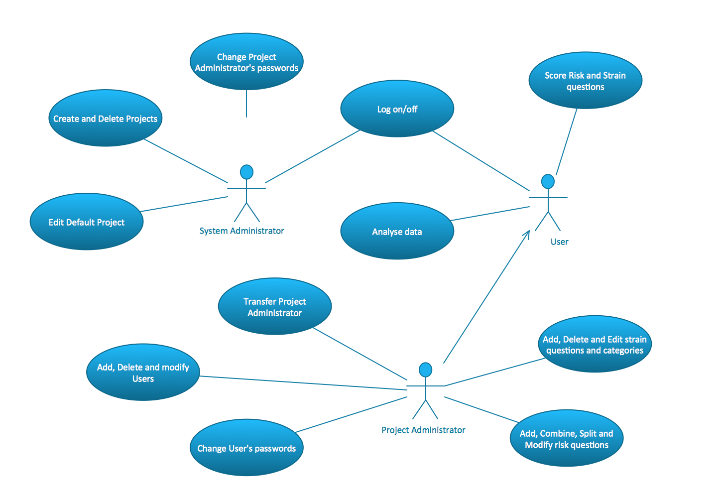
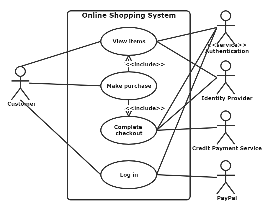
Uml Use Case Diagram For Empirical Software Engineering Research Fig 3 A use case diagram is a type of unified modeling language (uml) diagram that represents the interaction between actors (users or external systems) and a system under consideration to accomplish specific goals. it provides a high level view of the system’s functionality by illustrating the various ways users can interact with it. A uml use case diagram is the primary form of system software requirements for a new software program underdeveloped. use cases specify the expected behavior (what), and not the exact method of making it happen (how). use cases once specified can be denoted both textual and visual representation (i.e. use case diagram).

Uml Use Case Diagram Tutorial With Examples Change the status to use case diagram ‘started’ to facilitate progress tracking of each system. understand the system by referring to the brief and scope of the system detailed in the ‘list of system’ section of the document. step 1: draw the system boundary and name the system. step 2:. Uml is the modeling toolkit that you can use to build your diagrams. use cases are represented with a labeled oval shape. stick figures represent actors in the process, and the actor's participation in the system is modeled with a line between the actor and use case. to depict the system boundary, draw a box around the use case itself. A use case diagram is used to represent the dynamic behavior of a system. it encapsulates the system's functionality by incorporating use cases, actors, and their relationships. it models the tasks, services, and functions required by a system subsystem of an application. it depicts the high level functionality of a system and also tells how. An actor can be a person, another system, or a time event. a use case is a set of scenarios that describe how the system and the actor collaborate to achieve a common goal1. a scenario is a sequence of steps that describe what happens in a specific situation1. actors in use case modeling: actors are represented by stick figures in a use case.

What Are Use Case Diagrams In Software Engineering Design Talk A use case diagram is used to represent the dynamic behavior of a system. it encapsulates the system's functionality by incorporating use cases, actors, and their relationships. it models the tasks, services, and functions required by a system subsystem of an application. it depicts the high level functionality of a system and also tells how. An actor can be a person, another system, or a time event. a use case is a set of scenarios that describe how the system and the actor collaborate to achieve a common goal1. a scenario is a sequence of steps that describe what happens in a specific situation1. actors in use case modeling: actors are represented by stick figures in a use case. A uml (unified modeling language) use case diagram is a visual representation of the interactions between actors (users or external systems) and a system under consideration. it depicts the functionality or behavior of a system from the user’s perspective. use case diagrams capture the functional requirements of a system and help to identify. Professional uml graphics can quickly meet your work needs. step 1: create a new flowchart and add a uml diagram or uml use case diagram to the graphics area. step 2: drag and drop the uml use case diagram into the graph. step 3: mark the content and establish the relationship.

Uml Use Case Examples Of Common Scenarios Edrawmax A uml (unified modeling language) use case diagram is a visual representation of the interactions between actors (users or external systems) and a system under consideration. it depicts the functionality or behavior of a system from the user’s perspective. use case diagrams capture the functional requirements of a system and help to identify. Professional uml graphics can quickly meet your work needs. step 1: create a new flowchart and add a uml diagram or uml use case diagram to the graphics area. step 2: drag and drop the uml use case diagram into the graph. step 3: mark the content and establish the relationship.

Use Case Diagram Example In Software Engineering Design Talk

Comments are closed.