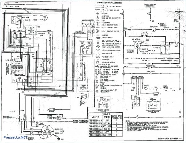
United Cool Air Wiring Diagram

United Cool Air Wiring Diagram Compressor #2 low press. smoke detector remote on off id16 tb (1) 93 328. close for proof of water flow (field wiring) (do not apply voltage) to remote on off (field wiring) to n.c. contacts on smoke detector (field wiring) 59. vdc u6 duct mounted return air temperature sensor (field wiring) . spt. Commercial. alpha aire gen 5. alpha aire ii. omegaair. varicool ez fit. verticool premium. air cooled start up. water cooled start up.

United Cool Air Wiring Diagram Free Wiring Diagram Install new filter drier. clean away debris. condenser air intake blocked reclaim excess from high pressure side of the overcharge of refrigerant system. page 31 installation, operation and maintenance manual c13 series item code problem probable cause solution check for control wiring to the free cool check wiring diagram and rewire. solenoid. This action will return the model number, job number and the wiring diagram for viewing as well as downloading note: only wiring diagrams for units shipped since november 2016 are available on the site, for older units please contact the factory directly at 717 843 4311. Show all. view and download united coolair c series installation manual online. air conditioning units 1 ton – 15 ton air cooled water cooled heat pump. c series air conditioner pdf manual download. also for: 4ca1901, 4ca1902, 4ca1903, 4ca1904, 4ca1905, 4ca1906, 4ca1907. Installation, operation and maintenance manual varicool ez fit wiring diagram to retrieve the unit wiring diagram, scan the wiring diagram qr code label affixed near the unit data tag this will link to www unitedcoolair com website scroll down to the serial search box and enter the unit serial number the serial number is a combination of the.

Electrical Wiring Diagrams For Air Conditioning Systems Part Two Show all. view and download united coolair c series installation manual online. air conditioning units 1 ton – 15 ton air cooled water cooled heat pump. c series air conditioner pdf manual download. also for: 4ca1901, 4ca1902, 4ca1903, 4ca1904, 4ca1905, 4ca1906, 4ca1907. Installation, operation and maintenance manual varicool ez fit wiring diagram to retrieve the unit wiring diagram, scan the wiring diagram qr code label affixed near the unit data tag this will link to www unitedcoolair com website scroll down to the serial search box and enter the unit serial number the serial number is a combination of the. Supply air duct the supply air duct connections are labeled “air out”. the connection size is 12” (3 ducts) or 14” (2 ducts) in diameter. connect the flexible air ducting as follows: 1. attach the flexible air ducting to the unit’s duct col lars making sure that air will not leak past the con nection collar by using appropriate round. These control the power, heat and fan. standard thermostats use 4 or 5 wires: r, w, g, y, and sometimes c. these control the power, heat, fan, and cooling. more advanced thermostats use 6 8 wires. the extra wires control additional hvac system features and settings, signaling a two stage cooling or heat pump system.

York Heat Pump Wiring Diagram Circuit Diagram Supply air duct the supply air duct connections are labeled “air out”. the connection size is 12” (3 ducts) or 14” (2 ducts) in diameter. connect the flexible air ducting as follows: 1. attach the flexible air ducting to the unit’s duct col lars making sure that air will not leak past the con nection collar by using appropriate round. These control the power, heat and fan. standard thermostats use 4 or 5 wires: r, w, g, y, and sometimes c. these control the power, heat, fan, and cooling. more advanced thermostats use 6 8 wires. the extra wires control additional hvac system features and settings, signaling a two stage cooling or heat pump system.

Electrical Wiring Diagrams For Air Conditioning Systems Part One

Comments are closed.