Uml Component Diagram Tutorial

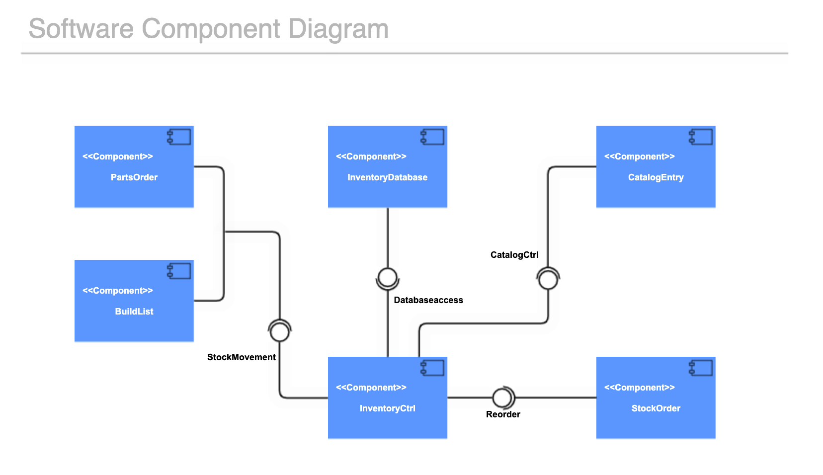
Uml Tutorial How To Draw Uml Component Diagram Youtube In uml, a component diagram visually represents how the components of a software system relate to one another. to build one, try using lucidchart’s custom component diagram shape library. component diagrams should communicate: the scope of your system. the overall structure of your software system. Learn what a component diagram is, how to draw one, and see examples of common scenarios. a component diagram shows the organization and dependency of system components using interfaces, ports, and dependencies.

Uml Component Diagram Tutorial The main purpose of a component diagram is to show the structural relationships between the components of a system. in uml, components are made up of software objects that have been classified to serve a similar purpose. components are considered autonomous, encapsulated units within a system or subsystem that provide one or more interfaces. Introduction. unified modeling language (uml) component diagrams serve as invaluable tools in the world of object oriented systems, offering a means to visualize, specify, and document component based systems. these diagrams play a crucial role in constructing executable systems through both forward and reverse engineering processes. To draw a component diagram, enable the uml and uml 2.5 shape libraries in draw.io. click on more shapes at the bottom of the shape panel. enable the uml and uml 2.5 checkboxes in the software section and click apply. component diagram shapes are spread out through both shape libraries. A component diagram breaks down the actual system under development into various high levels of functionality. each component is responsible for one clear aim within the entire system and only interacts with other essential elements on a need to know basis. the example above shows the internal components of a larger component: the data (account.

Uml Component Diagram Learn Types Of Symbol In Uml Component To draw a component diagram, enable the uml and uml 2.5 shape libraries in draw.io. click on more shapes at the bottom of the shape panel. enable the uml and uml 2.5 checkboxes in the software section and click apply. component diagram shapes are spread out through both shape libraries. A component diagram breaks down the actual system under development into various high levels of functionality. each component is responsible for one clear aim within the entire system and only interacts with other essential elements on a need to know basis. the example above shows the internal components of a larger component: the data (account. One way to visually organize such systems is through uml component diagrams. a uml component diagram shows how components relate to each other within a larger system. a system component is a module that’s part of a larger hardware and software system. it has its own inputs and outputs and specific interfaces with other system components. A uml (unified modeling language) component diagram consists of several elements that are used to model the high level structure of a system and its components. here are the key elements typically found in a uml component diagram: component: the primary element of the diagram, representing a high level, self contained software module or.

Uml Component Diagram Tutorial Gliffy By Perforce One way to visually organize such systems is through uml component diagrams. a uml component diagram shows how components relate to each other within a larger system. a system component is a module that’s part of a larger hardware and software system. it has its own inputs and outputs and specific interfaces with other system components. A uml (unified modeling language) component diagram consists of several elements that are used to model the high level structure of a system and its components. here are the key elements typically found in a uml component diagram: component: the primary element of the diagram, representing a high level, self contained software module or.

Comments are closed.