Trailer Wiring 7 Pin Diagram At Della Bennett Blog

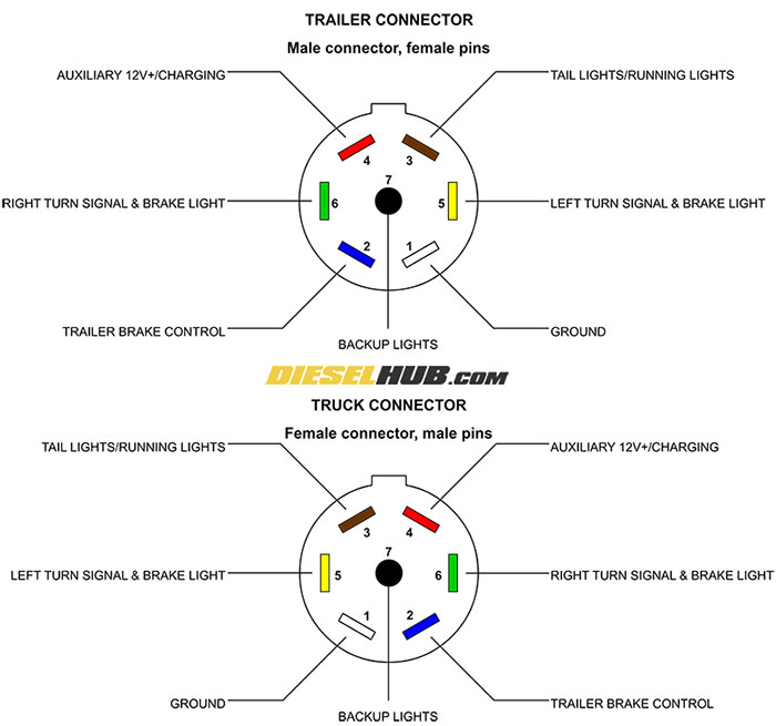
Trailer Wiring 7 Pin Diagram At Della Bennett Blog There are two key components that make up these systems: the 7 pin connectors and wiring mounted on both the vehicle and trailer. the connecting wires that join to circuits to carry signals and power. there are two common configurations of 7 way connectors: standard: the most widely used. reverse pin out: a configuration with opposing pin layouts. Understanding the 7 pin trailer plug wiring diagram and color code. the color code for a seven way trailer plug helps users correctly wire the connections for various functions. here is a standard color code and a diagram for a 7 way trailer plug: white: ground; blue: electric brakes; green: right turn signal and brake light.

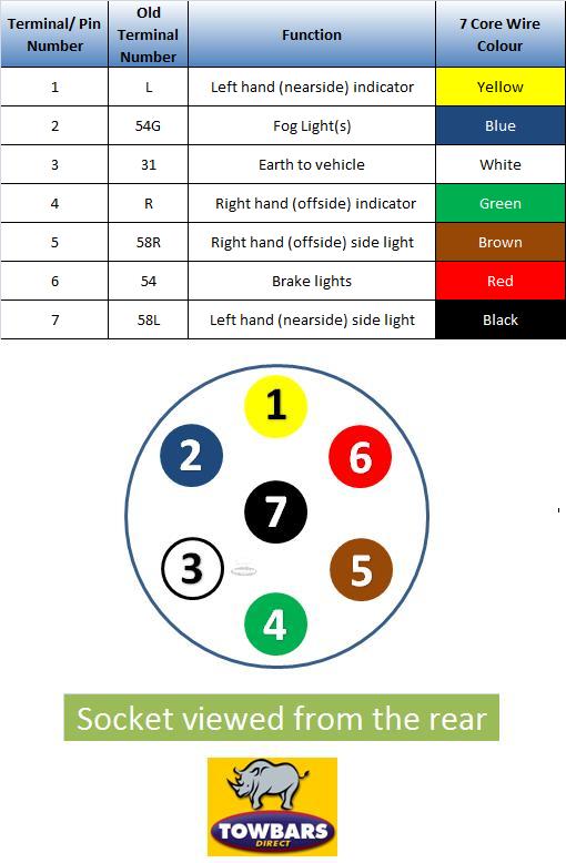
Trailer Wiring 7 Pin Diagram At Della Bennett Blog The minimum suggested wire size for a 7 way trailer plug is 16 gauge for the turn signals, brake lights, reverse lights, and running light wires. the suggested minimum for the ground, brake power, and battery hot lead wires is 12 gauge. if the wire is too thin, it can overheat and even catch fire when carrying electrical current. The following are the pin assignments for a 7 pin trailer connector: pin 1: ground – this pin is connected to the vehicle’s chassis ground. pin 2: electric brake – this pin is used to supply electric power to the trailer’s brake system. pin 3: tail lights – this pin provides power to the trailer’s tail lights. Step 4: connect the wires. now, connect the prepared wires to their corresponding terminals on the 7 pin trailer plug. use a screwdriver to tighten the screws on the terminals, ensuring a secure and proper connection. double check that each wire is connected to its correct terminal based on the wiring configuration. The seven pins in a trailer plug are labeled with numbers or letters for easy identification. here is a breakdown of the pin configuration: pin 1: this pin is used for the left turn signal or indicator lights. it connects to the corresponding wire on the towing vehicle. pin 2: the second pin is for the reverse lights.

Trailer Wiring 7 Pin Diagram At Della Bennett Blog Step 4: connect the wires. now, connect the prepared wires to their corresponding terminals on the 7 pin trailer plug. use a screwdriver to tighten the screws on the terminals, ensuring a secure and proper connection. double check that each wire is connected to its correct terminal based on the wiring configuration. The seven pins in a trailer plug are labeled with numbers or letters for easy identification. here is a breakdown of the pin configuration: pin 1: this pin is used for the left turn signal or indicator lights. it connects to the corresponding wire on the towing vehicle. pin 2: the second pin is for the reverse lights. Therefore, always refer to the device’s documentation or seek professional advice when working with unfamiliar connectors to ensure correct pin identification and usage. step 1: attach the ground wire. to begin the process of attaching the ground wire, locate the ground terminal on your electronic device or appliance. Step 4: strip the wires: use the wire strippers to strip a small portion of insulation off the ends of the wires. this will expose the bare copper wire for proper connection. step 5: connect the wires: connect each wire from the wiring harness to its corresponding wire on the seven pin trailer connector.

Comments are closed.