Trailer Connector Wiring Diagram 7 Way Printable Form Templates And

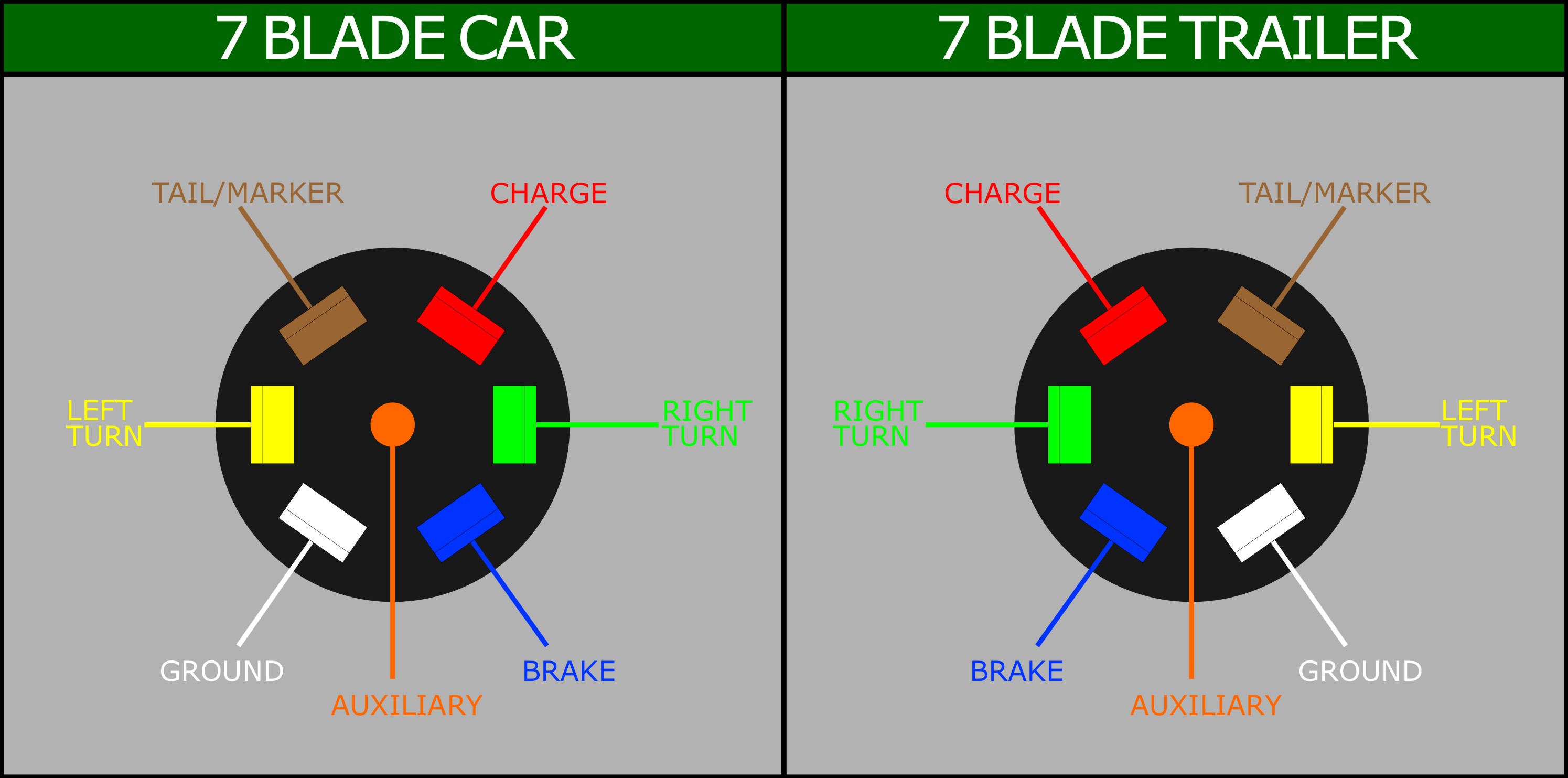
Trailer Connector Wiring Diagram 7 Way Printable Form Templates And 7 way plug wiring diagram standard wiring* post purpose wire color tm park light green ( ) battery feed black rt right turn brake light brown lt left turn brake light red s trailer electric brakes blue gd ground white a accessory yellow this is the most common (standard) wiring scheme for rv plugs and the one used by major auto manufacturers today. There are two key components that make up these systems: the 7 pin connectors and wiring mounted on both the vehicle and trailer. the connecting wires that join to circuits to carry signals and power. there are two common configurations of 7 way connectors: standard: the most widely used. reverse pin out: a configuration with opposing pin layouts.

Trailer Connector Wiring Diagram 7 Way Printable Form Templates And The 7 way trailer plug is a round 2" diameter connector that allows an additional pin for an auxiliary 12 volt power or backup lights. it is usually used for towing a heavy duty landscaping trailer, car trailer, boat trailer, horse trailer, travel trailer, construction trailer, and larger trailers. here at aj’s, we are all too familiar with. The 7 way trailer plug is around 2″ diameter connector that allows an additional pin for an auxiliary 12 volt power or backup lights. it is usually used for towing heavy duty cargo trailers, aluminum trailers, dump trailers, utility landscape trailers, equipment trailers, open car haulers and enclosed car haulers. The diagram for a 7 way trailer plug shows how these pins are arranged and what they are used for: pin 1: ground – this pin is used to provide a ground connection for the trailer. pin 2: electric brakes – this pin is used to supply power to the trailer’s electric brakes. pin 3: tail lights – this pin is used to provide power for the. For light duty trailers without brakes: the 4 way flat connector is most common. wiring configuration: white = ground – essential for all trailer electrical functions. brown = tail lights, side markers, and running lights – keeps your trailer visible and compliant with safety regulations. yellow = left turn signal & brake light – ensures.

Printable 7 Way Trailer Plug Wiring Diagram The diagram for a 7 way trailer plug shows how these pins are arranged and what they are used for: pin 1: ground – this pin is used to provide a ground connection for the trailer. pin 2: electric brakes – this pin is used to supply power to the trailer’s electric brakes. pin 3: tail lights – this pin is used to provide power for the. For light duty trailers without brakes: the 4 way flat connector is most common. wiring configuration: white = ground – essential for all trailer electrical functions. brown = tail lights, side markers, and running lights – keeps your trailer visible and compliant with safety regulations. yellow = left turn signal & brake light – ensures. Here is a step by step guide to connecting the ground wire: strip about half an inch of insulation off the end of the ground wire. insert the exposed wire into the appropriate terminal on the seven way trailer plug. tighten the screw or clamp on the terminal to secure the wire in place. Wiring a 7 way trailer connector is a relatively straightforward process, but it’s important to follow the correct steps to ensure a safe and functional connection. 1. gather the necessary tools and materials. before starting the wiring process, gather all the necessary tools and materials.

Comments are closed.