The Diagram Shows How Different Components Are Connected To Each Other

Component Diagram Tutorial Lucidchart An interconnect diagram is a visual representation that illustrates the connections between different components in a system. it provides a comprehensive view of how the different parts of the system are connected and interact with each other. in modern technology, interconnect diagrams are commonly used in various fields, including computer. In a circuit diagram, connecting lines are used to show how different components in a circuit are connected to each other. these lines represent the conductive pathways through which electric current flows. they are usually represented as straight lines, but can also be depicted as curved or angled lines, depending on the complexity of the circuit.

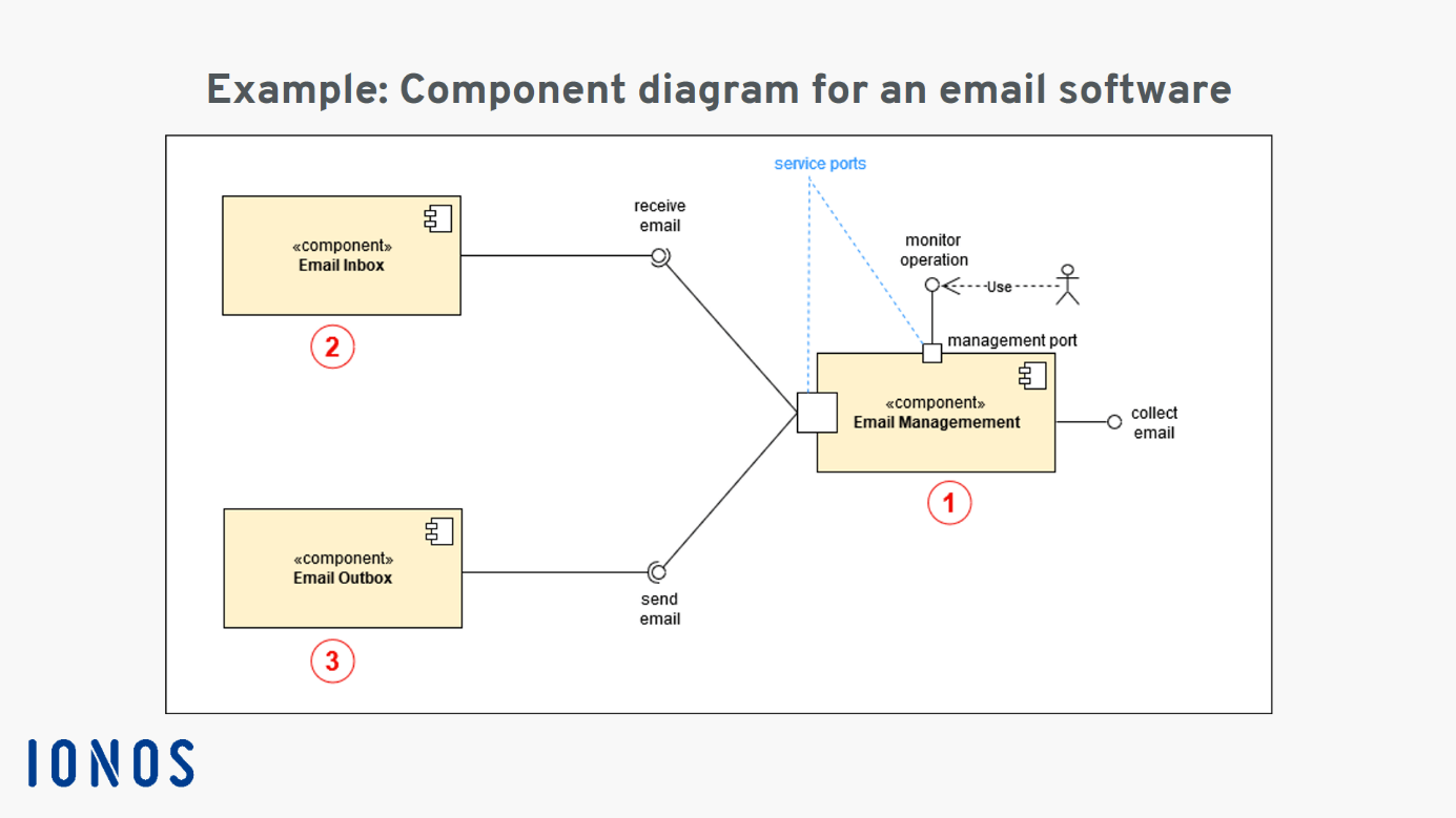
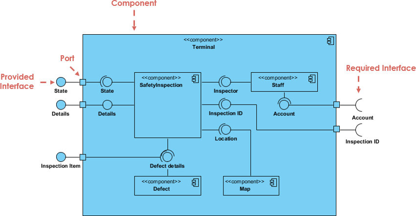
Free Editable Online Store Process Uml Component Diagram Edrawmax In Following are the steps you can follow when drawing a component diagram. step 1: figure out the purpose of the diagram and identify the artifacts such as the files, documents etc. in your system or application that you need to represent in your diagram. step 2: as you figure out the relationships between the elements you identified earlier. An electrical diagram or schematic is a visual representation of an electrical circuit. it shows how the components of the circuit are connected and how electricity flows through the circuit. understanding electrical diagrams and schematics is essential for electricians, technicians, and engineers who work with electrical systems. Once you understand the symbols, trace the connections between the components. a schematic diagram shows how the components are connected to each other and can include lines, dots, or other symbols to represent these connections. follow the lines and symbols to understand the flow of current through the circuit. 3. understand component values:. One way to visually organize such systems is through uml component diagrams. a uml component diagram shows how components relate to each other within a larger system. a system component is a module that’s part of a larger hardware and software system. it has its own inputs and outputs and specific interfaces with other system components.

Uml Component Diagram Explanation Drawing And Example Ionos Uk Once you understand the symbols, trace the connections between the components. a schematic diagram shows how the components are connected to each other and can include lines, dots, or other symbols to represent these connections. follow the lines and symbols to understand the flow of current through the circuit. 3. understand component values:. One way to visually organize such systems is through uml component diagrams. a uml component diagram shows how components relate to each other within a larger system. a system component is a module that’s part of a larger hardware and software system. it has its own inputs and outputs and specific interfaces with other system components. Understanding how a circuit diagram works can be a bit tricky. it comes from experience. you recognize the way some components are connected and identify known pieces of the schematic. in the circuit above for example, i would see the ldr together with the potentiometer in the middle. i know from experience that two resistors setup like this. Interfaces define how components interact with each other. interfaces are typically shown as small rectangles connected to components with a dashed line. dependency: indicates a relationship between two components where one depends on the other. dependencies are shown as dashed arrows pointing from the dependent component to the component it.

What Is Component Diagram Understanding how a circuit diagram works can be a bit tricky. it comes from experience. you recognize the way some components are connected and identify known pieces of the schematic. in the circuit above for example, i would see the ldr together with the potentiometer in the middle. i know from experience that two resistors setup like this. Interfaces define how components interact with each other. interfaces are typically shown as small rectangles connected to components with a dashed line. dependency: indicates a relationship between two components where one depends on the other. dependencies are shown as dashed arrows pointing from the dependent component to the component it.

Component Diagram Tutorial Lucidchart

Comments are closed.