Technical Drawing Dimension Symbols Design Talk

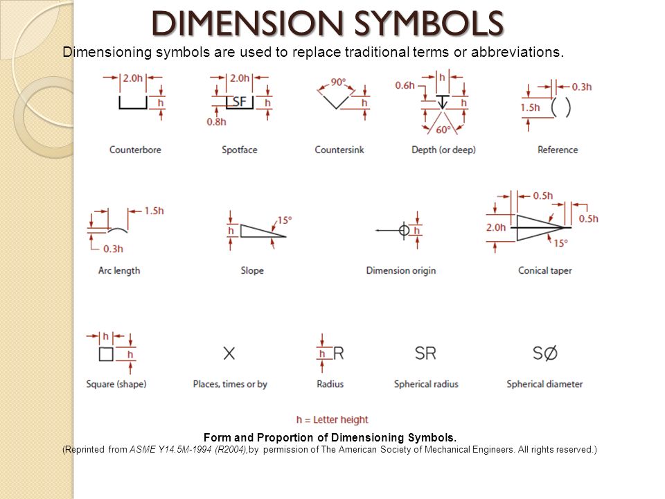
Technical Drawing Dimension Symbols Design Talk 1.3 symbol sizes are shown in the figures as values propor tional to the letter ‘h’. the letter ‘h’ represents the predominant character height on a drawing. if a symbol dimension is shown as 1.5h, and the predominant character height on the drawing is to be 3mm, then the symbol dimension is 4.5mm (1.5 x 3mm). Geometric dimensioning and tolerancing symbols you can either create your own library of gd&t symbols, or use one of autocad’s gd&t fonts to insert the symbols as text. the following tables show how to construct the symbols. any needed height h 2 h h 2 h 60° 2 h identification letter datum feature symbol datum target symbol target point and.

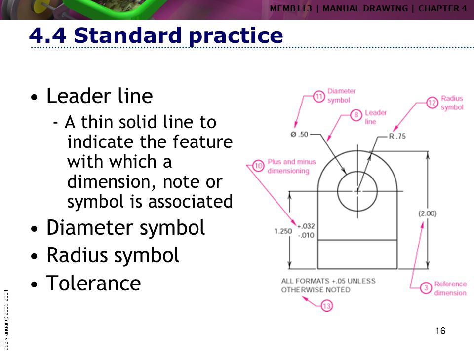
Technical Drawing Symbols And Their Meanings Design Talk A good design drawing can indicate all the details needed to produce a mechanical cnc milling part in an easy way. because there is no large space on a drawing to contain all the text to illustrate the image, abbreviations, and symbols are often used in engineering drawings to communicate the characteristics of the product to be manufactured. Radius ‘r’. radius can be for the inside and outside curved surface on the part. they are also used to show the fillets given to strengthen the edges at connecting faces. a radius dimension is preceded by an `r´. arcs are also dimensioned on drawing with a radius. for example, r6 means the circle has a radius of 6mm. Dimensions in brackets, such as (130.00) are so called redundant dimensions which could have been found by adding up other dimensions; in the case of this drawing: add 96.00 2(17.00) = 130.00 in figure 3.4.2 an angle is defined using the “e” symbol: this dimension means that the 3 “ears” are each 120 degrees apart. The basic drawing standards and conventions are the same regardless of what design tool you use to make the drawings. in learning drafting, we will approach it from the perspective of manual drafting. if the drawing is made without either instruments or cad, it is called a freehand sketch. figure 12 drawing tools. "assembly" drawings.

Technical Drawing Dimension Symbols Design Talk Dimensions in brackets, such as (130.00) are so called redundant dimensions which could have been found by adding up other dimensions; in the case of this drawing: add 96.00 2(17.00) = 130.00 in figure 3.4.2 an angle is defined using the “e” symbol: this dimension means that the 3 “ears” are each 120 degrees apart. The basic drawing standards and conventions are the same regardless of what design tool you use to make the drawings. in learning drafting, we will approach it from the perspective of manual drafting. if the drawing is made without either instruments or cad, it is called a freehand sketch. figure 12 drawing tools. "assembly" drawings. Dimension lines. dimension lines are used to indicate the size and location of features in an engineering drawing. they provide measurements that define the length, width, height, or diameter of objects, allowing for accurate replication and manufacturing. dimension lines are drawn as continuous, thin lines with arrowheads at each end. Understanding the symbols and conventions used in technical drawings is key to creating accurate designs. from line types that identify different parts of your design, to lettering styles that provide information about dimensions and other specifications, there are a few essential aspects you must understand when interpreting technical drawings.

Technical Drawing Dimensioning And Tolerancing Design Talk Dimension lines. dimension lines are used to indicate the size and location of features in an engineering drawing. they provide measurements that define the length, width, height, or diameter of objects, allowing for accurate replication and manufacturing. dimension lines are drawn as continuous, thin lines with arrowheads at each end. Understanding the symbols and conventions used in technical drawings is key to creating accurate designs. from line types that identify different parts of your design, to lettering styles that provide information about dimensions and other specifications, there are a few essential aspects you must understand when interpreting technical drawings.

Technical Drawing Dimension Symbols Design Talk

Comments are closed.