Symbols For Circuit Diagrams

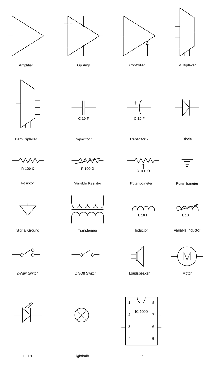
Circuit Diagram Symbols Lucidchart Use power source symbols to indicate alternating and direct currents in a circuit diagram. lucidchart has easy to use dialogs to let you switch the direction of the positive and negative charge icons, as well as the orientation and the voltage label. you can also make your circuit diagram stand out by adding a fill color with just one click. Electrical symbols & electronic circuit symbols of schematic diagram resistor, capacitor, inductor, relay, switch, wire, ground, diode, led, transistor, power.

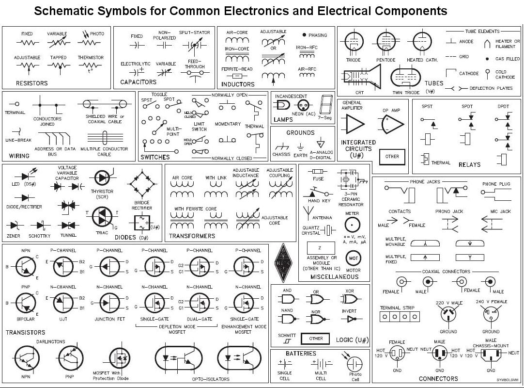
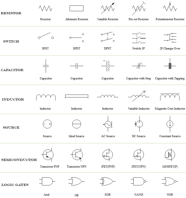
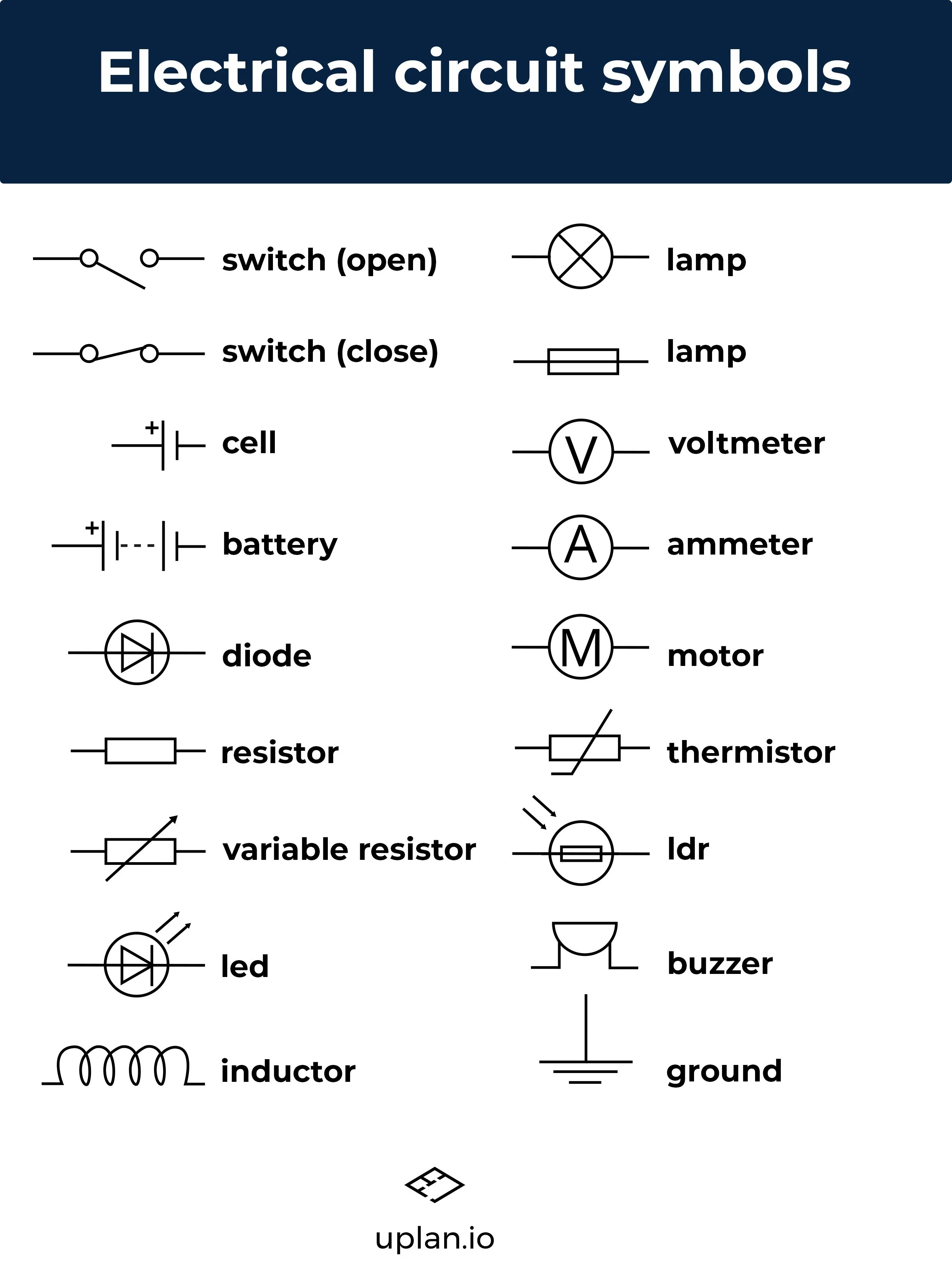
Circuit Schematic Symbols Circuit Diagrams Symbols Electrical Blog Understanding how a circuit diagram works can be a bit tricky. it comes from experience. you recognize the way some components are connected and identify known pieces of the schematic. in the circuit above for example, i would see the ldr together with the potentiometer in the middle. i know from experience that two resistors setup like this. The schematic symbols for op amps usually don’t show the pins that aren’t used in the circuit, as is the case for the lm358 symbol above where only five of the eight pins are shown. logic gates logic gates are electronic circuits that process signals that represent true or false values. Learn the graphical symbols of electrical and electronic components used in circuit diagrams and schematics. find the common and alternative symbols for power supply, resistor, capacitor, inductor, switch, diode, transistor and more. Learn how to use conventional circuit symbols to draw schematic diagrams of electric circuits. see examples of series and parallel connections and how they affect current, resistance and potential.

Symbols For Circuit Diagrams Learn the graphical symbols of electrical and electronic components used in circuit diagrams and schematics. find the common and alternative symbols for power supply, resistor, capacitor, inductor, switch, diode, transistor and more. Learn how to use conventional circuit symbols to draw schematic diagrams of electric circuits. see examples of series and parallel connections and how they affect current, resistance and potential. Schematic symbols (part 1) are you ready for a barrage of circuit components? here are some of the standardized, basic schematic symbols for various components. resistors. the most fundamental of circuit components and symbols! resistors on a schematic are usually represented by a few zig zag lines, with two terminals extending outward. In electronic circuits, there are many electronic symbols that are used to represent or identify a basic electronic or electrical device. they are mostly used to draw a circuit diagram and are standardized internationally by the ieee standard (ieee std 315) and the british standard (bs 3939).

Wiring Digrams Guide The Shortcut In Electrical Planning Schematic symbols (part 1) are you ready for a barrage of circuit components? here are some of the standardized, basic schematic symbols for various components. resistors. the most fundamental of circuit components and symbols! resistors on a schematic are usually represented by a few zig zag lines, with two terminals extending outward. In electronic circuits, there are many electronic symbols that are used to represent or identify a basic electronic or electrical device. they are mostly used to draw a circuit diagram and are standardized internationally by the ieee standard (ieee std 315) and the british standard (bs 3939).

Standard Electrical Circuit Symbols Stock Image T356 0593 Science

Comments are closed.