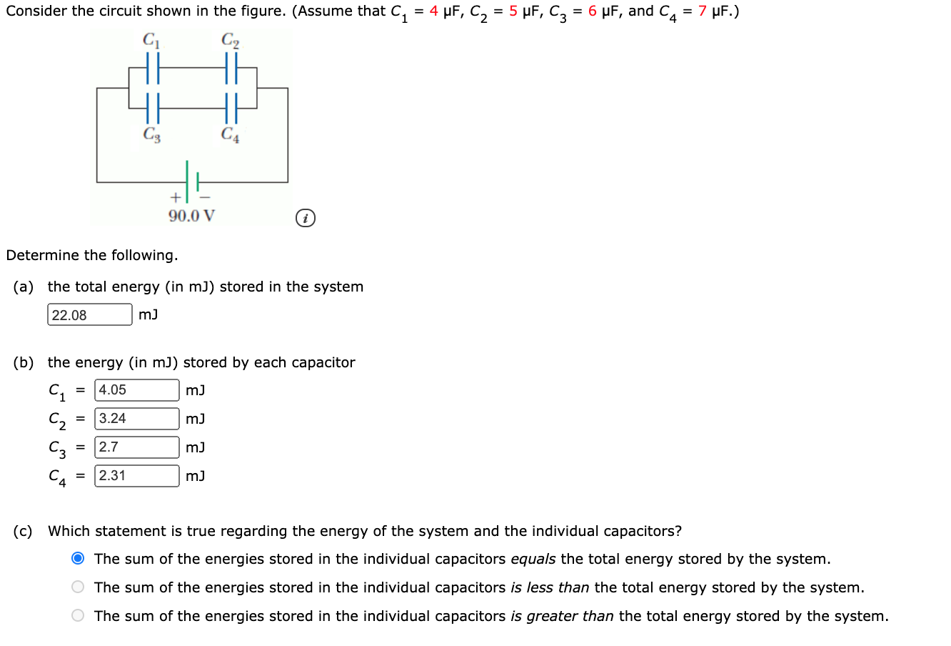
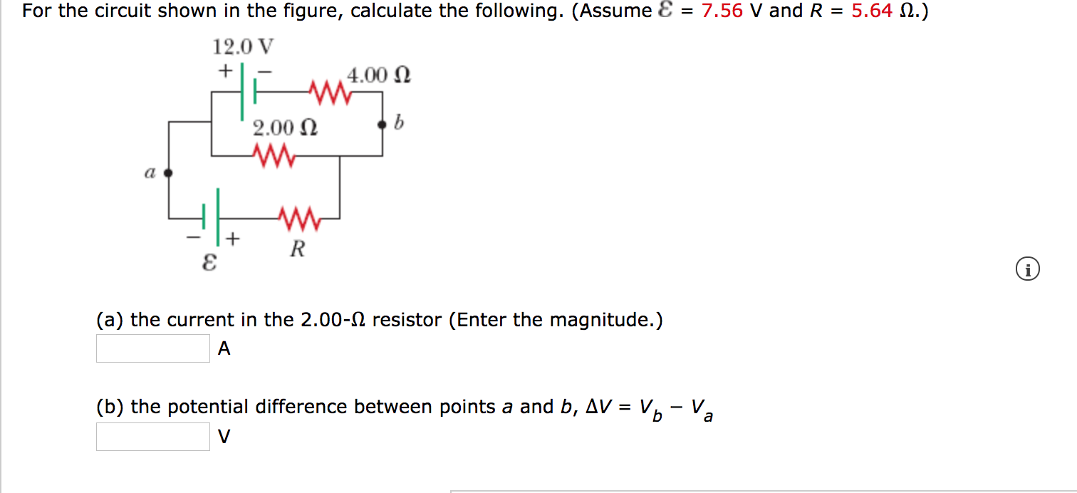
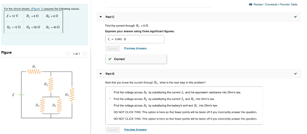
Solved For The Circuit Shown In The Following Figure Assume Chegg

Solved For The Circuit Shown In The Following Figure Assume Chegg Question: problem 5.for the circuit shown in figure 5 , assume va is not ∞. find the input output impedances and the voltage gain. (a) (b) (d) (e) problem 5. for the circuit shown in figure 5 , assume v a is not ∞. find the input output impedances and the voltage gain. there are 4 steps to solve this one. For the circuit shown in the figure, assume that r g = 6 3 0 ° Ω and r o = 1 9 Ω. assume an ideal transformer. find the magnitude of the equivalent impedance seen by the voltage. source (use two decimal places). there are 2 steps to solve this one.

Solved Consider The Circuit Shown In The Figure Assume Chegg Circuit problem solving procedure: 1) calculate the equivalent resistance of the circuit. first combine all the series resistors and then calculate the parallel ones. use the following equations: series: req = n ∑ i ri. parallel: 1 req = n ∑ i 1 ri. 2) use your result of equivalent resistance to find the total current coming out of the battery:. Here, we note the equivalent resistance as req. figure 10.3.5: (a) the original circuit of four resistors. (b) step 1: the resistors r3 and r4 are in series and the equivalent resistance is r34 = 10Ω (c) step 2: the reduced circuit shows resistors r2 and r34 are in parallel, with an equivalent resistance of r234 = 5Ω. Our expert help has broken down your problem into an easy to learn solution you can count on. question: 3.4: in the circuit shown in figure p3.4, assume r=5Ω and l=6h. also, let: find the energy stored in the inductor at t=9 (s) in joules. figure p3.4. 3. 4: in the circuit shown in figure p 3. 4, assume r = 5 Ω and l = 6 h. In the circuit shown in the following, determine v x and the power absorbed by the 1 2. resistor. there are 2 steps to solve this one. solution. answered by. electrical engineering expert. step 1. explanation:.

Solved For The Circuit Shown In The Figure Calculate The Chegg Our expert help has broken down your problem into an easy to learn solution you can count on. question: 3.4: in the circuit shown in figure p3.4, assume r=5Ω and l=6h. also, let: find the energy stored in the inductor at t=9 (s) in joules. figure p3.4. 3. 4: in the circuit shown in figure p 3. 4, assume r = 5 Ω and l = 6 h. In the circuit shown in the following, determine v x and the power absorbed by the 1 2. resistor. there are 2 steps to solve this one. solution. answered by. electrical engineering expert. step 1. explanation:. The designed circuit with component values and current and voltage values is shown in figure 5.8.2. the reader can check the calculations directly on the circuit diagram. figure 5.8.2 (b) refer to figure 5.8.1. the transistor remains in saturation as long as v d does not increase above v g by more than ∣ v t p ∣. No, it is a normal reading for this circuit. study with quizlet and memorize flashcards containing terms like refer to figure 8 2. replace the values shown with the following. solve for all the unknown values. i (t)= 0.6 a r1 = 470 Ω r2 = 360 Ω r3 = 510 Ω r4 = 430 Ω, refer to figure 8 5. replace the values shown with the following.

Solved For The Circuit Shown In The Figure Calculate The Chegg The designed circuit with component values and current and voltage values is shown in figure 5.8.2. the reader can check the calculations directly on the circuit diagram. figure 5.8.2 (b) refer to figure 5.8.1. the transistor remains in saturation as long as v d does not increase above v g by more than ∣ v t p ∣. No, it is a normal reading for this circuit. study with quizlet and memorize flashcards containing terms like refer to figure 8 2. replace the values shown with the following. solve for all the unknown values. i (t)= 0.6 a r1 = 470 Ω r2 = 360 Ω r3 = 510 Ω r4 = 430 Ω, refer to figure 8 5. replace the values shown with the following.

Solved For The Circuit Shown In The Figure Calculate The Chegg

Solved For The Circuit Shown Figure 1 Assume The Chegg

Comments are closed.