Solved For The Circuit Shown Figure 1 Assume The Chegg

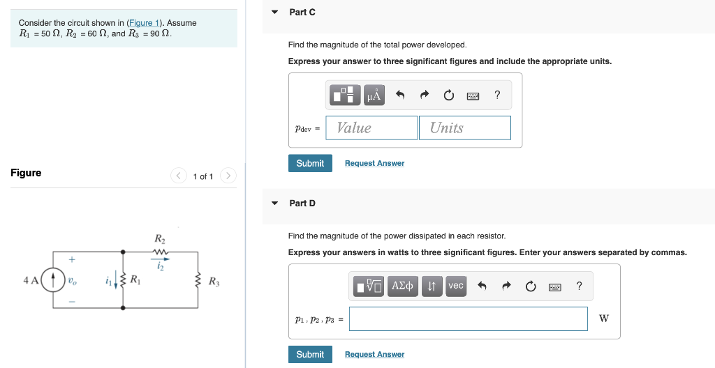
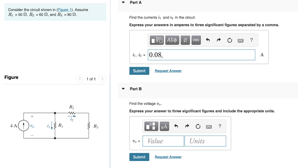
Solved Consider The Circuit Shown In Figure 1 Assume Chegg Our expert help has broken down your problem into an easy to learn solution you can count on. question: for the circuit shown, (figure 1) assume the following values. part a what is the equivalent resistance of this circuit? express your answer using four significant figures. there are 2 steps to solve this one. A) find the emf e1 in the circuit b) find the emf e2 in the circuit. for the circuit shown in (figure 1) , assume that e = 23.0 v and r = 6.35 ? . a) find the emf e1 in the circuit. b) find the emf e2 in the circuit. show transcribed image text. there are 2 steps to solve this one.

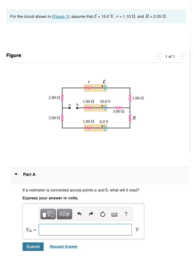
Solved For The Circuit Shown In Figure 1 Assume That Chegg Our expert help has broken down your problem into an easy to learn solution you can count on. question: for the circuit shown in figure 1, assume that e=20.0v and r=6.35. find the emf e1 and e2 in the circuit. in the circuit shown in figure 2 the 6.0 reisitor is consuming energy at a rate of 25.0j s when the current flows through as shown. Consider the circuit shown in (figure 1). assume e = 15 v.figure1 of 1the figure shows a rectangular circuit with two loops and three vertical wires. the circuit has a battery with electromotive force epsilon on the left vertical wire, a 3.0 microfarad capacitor on the middle wire, and a 6.0 microfarad capacitor on the right wire. Circuit problem solving procedure: 1) calculate the equivalent resistance of the circuit. first combine all the series resistors and then calculate the parallel ones. use the following equations: series: req = n ∑ i ri. parallel: 1 req = n ∑ i 1 ri. 2) use your result of equivalent resistance to find the total current coming out of the battery:. Here, we note the equivalent resistance as req. figure 10.3.5: (a) the original circuit of four resistors. (b) step 1: the resistors r3 and r4 are in series and the equivalent resistance is r34 = 10Ω (c) step 2: the reduced circuit shows resistors r2 and r34 are in parallel, with an equivalent resistance of r234 = 5Ω.

Solved Consider The Circuit Shown In Figure 1 Assume Chegg Circuit problem solving procedure: 1) calculate the equivalent resistance of the circuit. first combine all the series resistors and then calculate the parallel ones. use the following equations: series: req = n ∑ i ri. parallel: 1 req = n ∑ i 1 ri. 2) use your result of equivalent resistance to find the total current coming out of the battery:. Here, we note the equivalent resistance as req. figure 10.3.5: (a) the original circuit of four resistors. (b) step 1: the resistors r3 and r4 are in series and the equivalent resistance is r34 = 10Ω (c) step 2: the reduced circuit shows resistors r2 and r34 are in parallel, with an equivalent resistance of r234 = 5Ω. Parallel rlc circuit the rlc circuit shown on figure 6 is called the parallel rlc circuit. it is driven by the dc current source is whose time evolution is shown on figure 7. is r l c il(t) v ir(t) ic(t) figure 6 t is 0 figure 7 our goal is to determine the current il(t) and the voltage v(t) for t>0. we proceed as follows: 1. Forced response of rc circuits. for the circuit shown on figure 15 the switch is closed at t=0. this corresponds to a step function for the source voltage vs as shown on figure 16.we would like to obtain the capacitor voltage vc as a function of time. the voltage across the capacitor at t=0 (the initial voltage) is vo.

Solved For The Circuit Shown Figure 1 Assume The Chegg Parallel rlc circuit the rlc circuit shown on figure 6 is called the parallel rlc circuit. it is driven by the dc current source is whose time evolution is shown on figure 7. is r l c il(t) v ir(t) ic(t) figure 6 t is 0 figure 7 our goal is to determine the current il(t) and the voltage v(t) for t>0. we proceed as follows: 1. Forced response of rc circuits. for the circuit shown on figure 15 the switch is closed at t=0. this corresponds to a step function for the source voltage vs as shown on figure 16.we would like to obtain the capacitor voltage vc as a function of time. the voltage across the capacitor at t=0 (the initial voltage) is vo.

Solved In The Circuit Shown In Figure 1 Assume That I1 Chegg

Solved Figure In The Circuit Shown In Figure 1 Assume Chegg

Comments are closed.