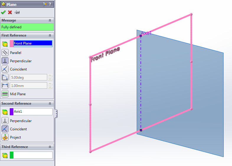
Solidworks Intro To Planes Step 2

Solidworks Intro To Planes Step 2 Youtube Solidworks intro to planes step 2. 2. preparing a sketching plane. to start creating the sketch, click on the “sketch” tab towards the upper left and then select the “sketch” icon. a new message replaces the design tree, asking you to select a plane on which to create the sketch. at this step, planes should appear in the workspace.

How To Design Fighter Jet Air Plane In Solidworks Part 2 Advance Click new (standard toolbar) or file > new. in the new solidworks document dialog box, click drawing and click ok. the sheet format size dialog box appears where you can set the drawing sheet parameters. in the list, select a3 (iso) and click ok. However, the quickest way to start a new sketch from a default plane, and really any plane or face, is to left or right click on the desired plane (in the featuremanager design tree or graphics area) and select the “sketch” icon (figure 2.6). this puts you right into the sketch environment. the sketch environment is to the solidworks user. Solidworks uses a “parametric” approach to modeling. this is different that a standard 2d cad program like autocad. when you use solidworks, you capture the design intent by using features and constraints – a rich database of digital information is created about the part in the background. Steps to create a plane at an angle in solidworks. to create a plane at an angle in solidworks, follow these steps: 1. select the plane tool from the create tab. 2. click on the face or edge of the solid model where you want to create the plane. 3.

How To Connect Two Planes In Solidworks At Lillian Pickney Blog Solidworks uses a “parametric” approach to modeling. this is different that a standard 2d cad program like autocad. when you use solidworks, you capture the design intent by using features and constraints – a rich database of digital information is created about the part in the background. Steps to create a plane at an angle in solidworks. to create a plane at an angle in solidworks, follow these steps: 1. select the plane tool from the create tab. 2. click on the face or edge of the solid model where you want to create the plane. 3. Step 1: begin by activating the reference plane tool. you can find it under the “features” tab or by right clicking on the “reference geometry” folder in the featuremanager design tree. step 2: select a reference plane or planar face to define the orientation of your new perpendicular plane. step 3: specify the distance or offset value. To insert a plane in solidworks, follow these steps: launch solidworks and open the desired part or assembly document. go to the features tab in the commandmanager and click on the plane icon or navigate to insert → reference geometry → plane. a dialog box will appear, allowing you to define the properties of the plane.

How To Create Solidworks Planes Grabcad Tutorials Step 1: begin by activating the reference plane tool. you can find it under the “features” tab or by right clicking on the “reference geometry” folder in the featuremanager design tree. step 2: select a reference plane or planar face to define the orientation of your new perpendicular plane. step 3: specify the distance or offset value. To insert a plane in solidworks, follow these steps: launch solidworks and open the desired part or assembly document. go to the features tab in the commandmanager and click on the plane icon or navigate to insert → reference geometry → plane. a dialog box will appear, allowing you to define the properties of the plane.

How To Create Solidworks Planes Grabcad Tutorials

Comments are closed.