Small Block Ford Cooling Diagram

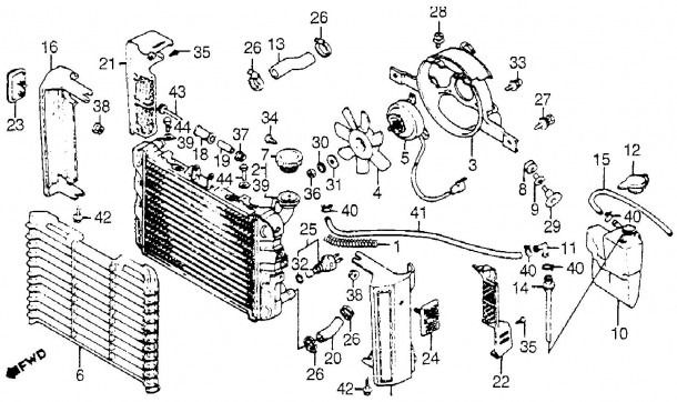
Small Block Ford Cooling Diagram Beginning in 1970, 302 and 351w small block fords received a new water pump casting (d0az 8501 c) with the inlet on the left hand side of the engine. boss 302s for 1969 were fitted with a 1969 specific high flow water pump (c9zz 8501 a). a year later, in 1970, the boss 302 engine was fitted with the d0zz 8501 b water pump. 558 posts · joined 2006. #1 · feb 9, 2020. tempered with the old adage that ford never spent a dime he (they) didn’t have to, isn’t the thermostat bypass on the small block ford cooling system (the little 90° hose that runs from the thermostat housing to the water pump) a bit of a redundancy, given that the heater also allows the same.

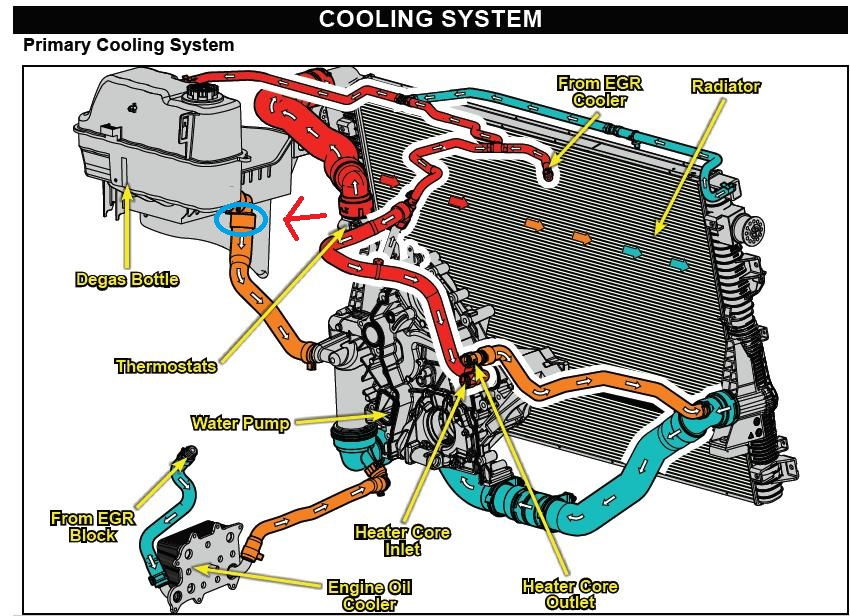
Small Block Ford Cooling Diagram Small block ford v 8s were fitted with two types of air conditioning compressors early on. the york compressor (shown) is cast aluminum and lighter than the cast iron tecumseh compressor. they are interchangeable. this is a 1967 289 with the york compressor and belt tension adjustment down at the water pump. Hi, does anyone have a diagram showing the flow of coolant around the engine radiator etc. i have a 302 engine and the two small outlets on the water pump have been bridged i assume these were for the heater matrix, and at the back of the heads there seems to be coolant ways which have been. Small block ford tutorial. oy vey. small block ford is one of the most difficult engines for customers to understand when it comes to accessory drives. vast amounts of time have gone into dissecting the various combinations of sbf. collecting samples of water pumps, balancers, timing covers and blocks. measuring, re measuring and test fitting. The baby ford small block had the same 3.000 inch stroke as the 302 with a smaller 3.68 inch bore. it had 255 specific cylinder heads with smaller combustion chambers and valves with round ports, and absolutely no performance potential whatsoever. the 255 was a very short lived chapter in small block ford history and with good reason.

Small Block Ford Cooling Diagram Small block ford tutorial. oy vey. small block ford is one of the most difficult engines for customers to understand when it comes to accessory drives. vast amounts of time have gone into dissecting the various combinations of sbf. collecting samples of water pumps, balancers, timing covers and blocks. measuring, re measuring and test fitting. The baby ford small block had the same 3.000 inch stroke as the 302 with a smaller 3.68 inch bore. it had 255 specific cylinder heads with smaller combustion chambers and valves with round ports, and absolutely no performance potential whatsoever. the 255 was a very short lived chapter in small block ford history and with good reason. You also want the coolant flowing into the lower nipple of the heater core, and returning to the engine from the upper nipple. this ensures the core is full of coolant. hooking it up the other way could result in a waterfall sound coming out of the heater box. pre power stroke diesel (7.3l idi & 6.9l) coolant flow <<< direction. The passenger side radiator inlet, conventional rotation, aluminum water pump originally stock on some early small block fords (generally 1964 to early 1965) didn't have a rear cover.
Small Block Ford Cooling Diagram You also want the coolant flowing into the lower nipple of the heater core, and returning to the engine from the upper nipple. this ensures the core is full of coolant. hooking it up the other way could result in a waterfall sound coming out of the heater box. pre power stroke diesel (7.3l idi & 6.9l) coolant flow <<< direction. The passenger side radiator inlet, conventional rotation, aluminum water pump originally stock on some early small block fords (generally 1964 to early 1965) didn't have a rear cover.

Small Block Ford Cooling Diagram
Small Block Ford Cooling Diagram

Comments are closed.