Single Electric Fan Wiring Diagram

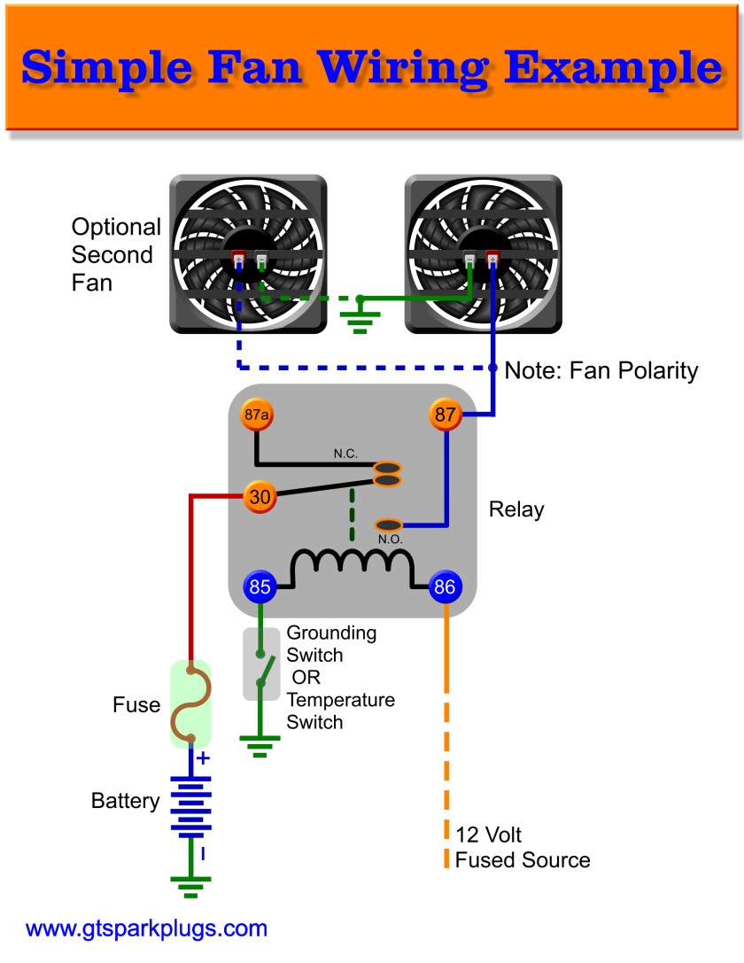
Single Electric Fan Relay Wiring Diagram With dual cooling fans, there are two methods for wiring up the relay kit. this is based on the draw from the fans, if the fans are larger and draw more than 15 amps each, it's recommended to install a second relay kit as shown below. for smaller fans, both fans can be connected to a single relay as shown above, and the proper fuse should be. 87 (red wire) connects to the positive wire on the electric fan. 30 (other red wire) needs constant 12 volt power from the battery. 86 (gray white wire) goes to the ignition switch.

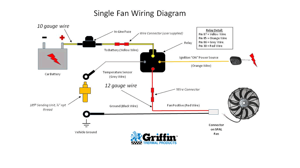
Single Electric Fan Wiring Diagram Here are some tips to help you with the wiring process: 1. use the correct wire gauge: when wiring an electric fan, it is crucial to use the correct wire gauge. the wire gauge should be suitable for the amperage rating of the fan. using a wire that is too thin can cause overheating and potentially start a fire. 2. Wire connector in line fuse relay connector on spal fan wire connector (user supplied) 185o sending unit, ¼” npt thread car battery vehicle ground ground (black wire) single fan wiring diagram (orange wire) relay detail: pin 87 = yellow wire pin 85 = orange wire pin 86 = grey wire pin 30 = red wire optional cooling fan override switch 10. This video shows how to easily wire an electric radiator fan circuit into any car. this fan wiring diagram includes a fan relay, a temperature switch, and a. A: to quickly test the override circuit, disconnect the green wire and run a jumper wire directly to the positive ( ) terminal on the battery. the electric fan should start immediately. if fan started, reattach the green wire to the proper ( ) wire on the a c clutch or manual switch. warning: installation of accessories should only be.

Electric Fan Wiring Diagram Fan Single Wiring Diagram Cooling Relay This video shows how to easily wire an electric radiator fan circuit into any car. this fan wiring diagram includes a fan relay, a temperature switch, and a. A: to quickly test the override circuit, disconnect the green wire and run a jumper wire directly to the positive ( ) terminal on the battery. the electric fan should start immediately. if fan started, reattach the green wire to the proper ( ) wire on the a c clutch or manual switch. warning: installation of accessories should only be. The wiring diagram provides a visual representation of how the different components of the system are connected, allowing for proper installation and troubleshooting. the automotive electric fan relay wiring diagram typically includes several components such as the fan motor, relay, temperature sensor, fuse, and power source. Ceiling fan diagrams fan wiring diagram with power entering the switch box and the load wire connected to the blue wire for the light and the black wire for the fan motor. the above ceiling fan wiring diagram depicts the power going into the switches’ electrical box first. then a switched hot and a neutral go up to the ceiling mounted.

Comments are closed.