Scr Half Wave Rectifier Circuit Diagram

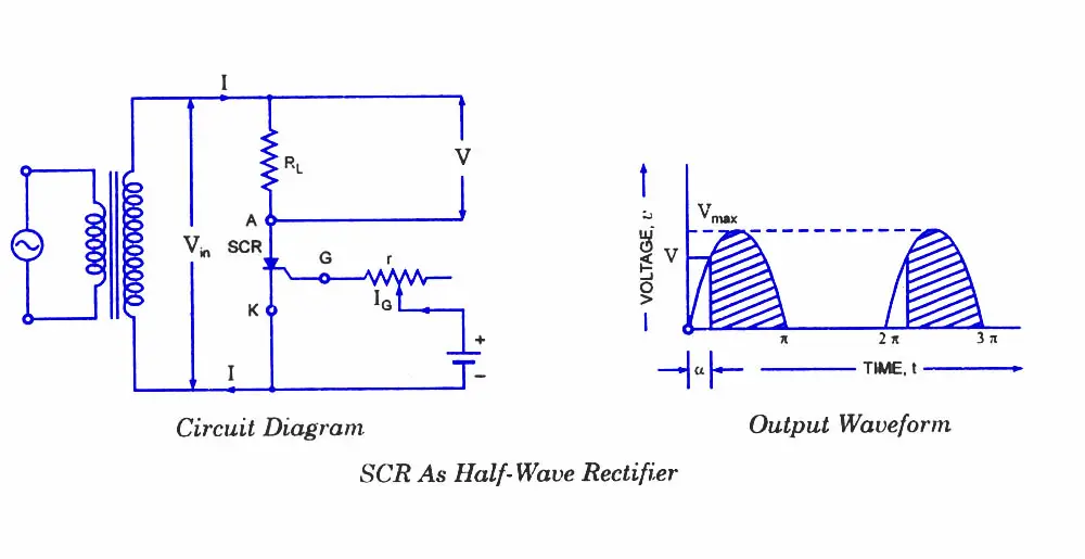
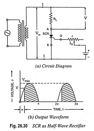
Scr As Half Wave Rectifier The circuit using an scr as an half wave rectifier is shown in figure. the ac supply to be rectified is applied to the primary of the transformer ensuring that the negative voltage appearing at the secondary of the transformer is less than reverse breakdown voltage of the scr. the load resistance r l is connected in series with anode. The circuit using an scr as half wave rectifier is shown in fig. 26.30 (a). the ac supply to be rectified is applied to the primary of the transformer ensuring that the negative voltage appearing at the secondary of the transformer is less than reverse breakdown voltage of the scr. the load resistance r l is connected in series with anode.

Scr As Half Wave Rectifier Circuit Diagram Eeeguide Com Here, an scr is positioned in a circuit to control power to a load from an ac source. scr control of ac power. being a unidirectional (one way) device, at most, we can only deliver half wave power to the load, in the half cycle of ac where the supply voltage polarity is positive on the top and negative on the bottom. A half wave rectifier is defined as a type of rectifier that only allows one half cycle of an ac voltage waveform to pass, blocking the other half cycle. half wave rectifiers are used to convert ac voltage to dc voltage, and only require a single diode to construct. a rectifier is a device that converts alternating current (ac) to direct. Figure 16 shows a particularly effective yet simple variable speed regulator circuit. this uses an scr as the control element and feeds half wave power to the motor (this causes a 20% reduction in maximum available speed power), but in the off half cycles, the back emf of the motor is sensed by the scr and used to give automatic adjustment of. The scr (thyristor) is a three terminal device (anode, cathode and gate) with four layers of alternating p and n type material. the gate terminal is used to control the scr, the anode (a) and cathode (k) are connected in series with the load. the scr is just a controlled diode. in single phase half wave rectifier, only one thyristor is used to.

Circuit Diagram Of Half Wave Rectifier Using Scr Circuit Diagram Figure 16 shows a particularly effective yet simple variable speed regulator circuit. this uses an scr as the control element and feeds half wave power to the motor (this causes a 20% reduction in maximum available speed power), but in the off half cycles, the back emf of the motor is sensed by the scr and used to give automatic adjustment of. The scr (thyristor) is a three terminal device (anode, cathode and gate) with four layers of alternating p and n type material. the gate terminal is used to control the scr, the anode (a) and cathode (k) are connected in series with the load. the scr is just a controlled diode. in single phase half wave rectifier, only one thyristor is used to. Single phase half wave controlled rectifier, as the name suggests, is a rectifier circuit which converts ac input into dc output only for positive half cycle of the ac input supply. the word “controlled” means that, we can change the starting point of load current by controlling the firing angle of scr. these words might seem a lot technical. This is the same voltage as for a half wave diode circuit. therefore, if the scr is fired at α = 0 o, the circuit acts like a diode rectifier. the normal average voltage is. v n as a function of α is known as the control characteristic of the rectifier and is shown in figure 2. control characteristic for a half wave rectifier.

Comments are closed.