Rule Mate Automatic Bilge Pump Wiring Diagram Wiring Diagram

Rule Mate Bilge Pump Wiring Rule mate intelligence rule mate bilge pumps have built in programming that can sense when the pump is running but not pumping water to protect the pump, vessel, and the vessel’s batteries. if debris covers the sensor or the pump becomes air bound, the pump will stop running and begin to “check” for water every 2.5 minutes. Rule mate 500 water pump pdf manual download. also for: rule mate 800, rule mate 1100. the bilge pump inlet shall be located so that excess bilge water can be.

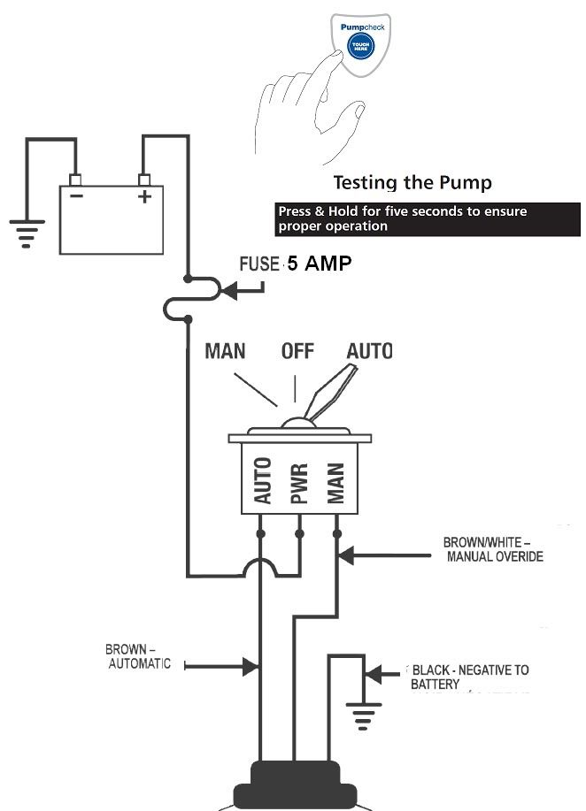
Rule Mate 500 Automatic Bilge Pump Wiring Diagram Clear pump inlets from debris. if seacocks are fitted in the fore and aft peak bulkheads, they shall be kept closed and shall only be opened to let water drain into the main bilges. 2.5 min 0.5 sec 2.5 min 0.5 sec 2.5 min 0.5 sec.75" (2cm) off 1.5" (3.8cm) on off on off on on how fully automatic bilge pumps work: rule automatic bilge pumps. The automatic pumps feature two positive leads: an automatic (brown) and a manual override (brown with a white stripe). automatic pump wiring 3 wires 3 position panel switch constant auto manual override constant auto no manual override on 12 volt pump: minimum voltage of 10.5 volts required. on 24 volt pump: minimum voltage of 21 volts. To begin, it is important to gather all the necessary materials and tools for the installation. you will need the rule 1500 automatic bilge pump, wiring, connectors, fuse holder, fuse, switch panel, and a battery. make sure all the components are compatible and of high quality to ensure proper performance. once you have all the materials ready. The rule mate 1100 automatic bilge pump is powered by an internally regulated 8 14 volt power source. its ability to recognize wiring diagrams provides a wide range of control options, allowing customized programming of the water level in the bilge.

Rule Automatic Bilge Pump Wiring Diagram Wiring Diagram To begin, it is important to gather all the necessary materials and tools for the installation. you will need the rule 1500 automatic bilge pump, wiring, connectors, fuse holder, fuse, switch panel, and a battery. make sure all the components are compatible and of high quality to ensure proper performance. once you have all the materials ready. The rule mate 1100 automatic bilge pump is powered by an internally regulated 8 14 volt power source. its ability to recognize wiring diagrams provides a wide range of control options, allowing customized programming of the water level in the bilge. Rule mate 2000 wiring is specifically designed to provide reliable and efficient power to your boat’s bilge pump, ensuring the safety and smooth operation of your vessel. this wiring system comes equipped with an automatic float switch, eliminating the need for manual activation and allowing for hassle free operation. A wiring diagram is a visual representation of the electrical connections that need to be made in order to install the rule mate 2000 bilge pump. it shows how the various components of the pump, such as the switch, float switch, and pump motor, are connected to each other and to the boat’s electrical system.

Rule Automatic Bilge Pump Wiring Rule mate 2000 wiring is specifically designed to provide reliable and efficient power to your boat’s bilge pump, ensuring the safety and smooth operation of your vessel. this wiring system comes equipped with an automatic float switch, eliminating the need for manual activation and allowing for hassle free operation. A wiring diagram is a visual representation of the electrical connections that need to be made in order to install the rule mate 2000 bilge pump. it shows how the various components of the pump, such as the switch, float switch, and pump motor, are connected to each other and to the boat’s electrical system.

Comments are closed.