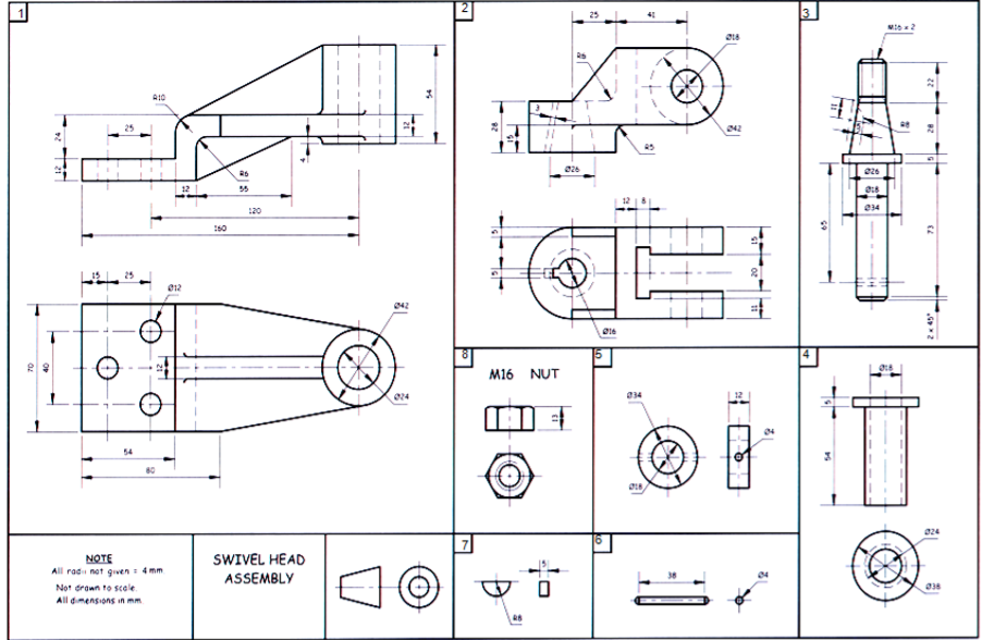
Resultado De Imagen Para Detailed Assembly Drawing Isometric Drawing

Resultado De Imagen Para Detailed Assembly Drawing Autocad Isometric I am mechanical engineer, i am a professional in drafting and designing cad applications for 4 years now. for sketches and images, i will design any kind of design in 3d models and 2d drawings using solidworks and autocad.i will do as much as possible to be realistic and bring your ideas to designs that can be implemented to give my best service. #solidworks, #2ddrawings, #3dmodel, #. Jan 14, 2018 explore mush360 cantos's board "assembly drawings with dimensions" on pinterest. see more ideas about mechanical engineering design, mechanical design, technical drawing.

Detailed Assembly Drawing Assembly Drawing 3d Drawing Images 3d An isometric projection is a representation of a view of an object at 35o 16’ elevation and 45o azimuth. the principal axes of projection are obtained by rotating a cube through 45o about a vertical axis, then tilting it downward at 35o 16’ (35.27o) as shown in fig. 9.1a. a downward tilt of the cube shows the top face while an upward tilt. Resultado de imagen para detailed assembly drawing. mechanics drawing. solidworks tutorial. isometric drawing exercises. 3d drawing techniques. solid works. Isometric drawing. the representation of the object in figure 2 is called an isometric drawing. this is one of a family of three dimensional views called pictorial drawings. in an isometric drawing, the object's vertical lines are drawn vertically, and the horizontal lines in the width and depth planes are shown at 30 degrees to the horizontal. They are meant for item identification, standard requirements, and labeling the sequence for assembly. typically, assembly drawings are produced in two forms: 2d sectioned view or exploded pictorial view. the drawings include: orthogonal sections, plans, and elevations, explaining the assembling process. 3d view – showing the final assembled.

Resultado De Imagen De Detailed Assembly Drawing Mechanical Design Isometric drawing. the representation of the object in figure 2 is called an isometric drawing. this is one of a family of three dimensional views called pictorial drawings. in an isometric drawing, the object's vertical lines are drawn vertically, and the horizontal lines in the width and depth planes are shown at 30 degrees to the horizontal. They are meant for item identification, standard requirements, and labeling the sequence for assembly. typically, assembly drawings are produced in two forms: 2d sectioned view or exploded pictorial view. the drawings include: orthogonal sections, plans, and elevations, explaining the assembling process. 3d view – showing the final assembled. Autocad isometric drawing. mechanical drawings. machining metal projects. solid works. 3d sketch. resultado de imagen de detailed assembly drawing. drafting drawing. Getting started with isometric drawing in draftsight. to start creating isometric drawings in draftsight, you need to configure the isometric grid. you can switch your grid settings to isometric by typing isometricgrid at the command prompt or pressing f5. this aligns your grid to the isometric axes, simplifying the drawing process.

Resultado De Imagen De Detailed Assembly Drawing Mechanical Design Autocad isometric drawing. mechanical drawings. machining metal projects. solid works. 3d sketch. resultado de imagen de detailed assembly drawing. drafting drawing. Getting started with isometric drawing in draftsight. to start creating isometric drawings in draftsight, you need to configure the isometric grid. you can switch your grid settings to isometric by typing isometricgrid at the command prompt or pressing f5. this aligns your grid to the isometric axes, simplifying the drawing process.

Assembly And Details Machine Drawing Pdf Autocad Drawing Technical

Solved Given An Isometric View And Detail Drawings Of A Chegg

Comments are closed.