Resistor Capacitor In Series

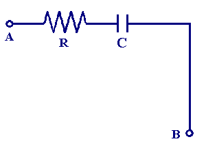
Ac Circuit Resistor And A Capacitor In Series Youtube Because the resistor’s resistance is a real number (5 Ω ∠ 0°, or 5 j0 Ω), and the capacitor’s reactance is an imaginary number (26.5258 Ω ∠ 90°, or 0 j26.5258 Ω), the combined effect of the two components will be an opposition to current equal to the complex sum of the two numbers. the term for this complex opposition to. An \(rc\) circuit is one that has both a resistor and a capacitor. the time constant \(\tau\) for an \(rc\) circuit is \(\tau = rc\). when an initially uncharged \((v 0=0\) at \(t=0)\) capacitor in series with a resistor is charged by a dc voltage source, the voltage rises, asymptotically approaching the emf of the voltage source; as a function.

Capacitor In Series Line At Thomas Hay Blog A resistor–capacitor circuit (rc circuit), or rc filter or rc network, is an electric circuit composed of resistors and capacitors. it may be driven by a voltage or current source and these will produce different responses. a first order rc circuit is composed of one resistor and one capacitor and is the simplest type of rc circuit. An rc circuit (also known as an rc filter or rc network) stands for a resistor capacitor circuit. an rc circuit is defined as an electrical circuit composed of the passive circuit components of a resistor (r) and capacitor (c), driven by a voltage source or current source. due to the presence of a resistor in the ideal form of the circuit, an. For example if we take the above circuit with a resistor of 100 Ω and capacitor of 1x10 6 f and apply a sinusoidal voltage at a frequency of 10 hz, the capacitative reactance can be calculated as: xc = 1 (2 x 3.1415 x 10 x 1x10 6) = 15.9x10³ Ω. and so the total impedance in rectangular form is. z = r j xc = 100 j 15.9x10³. Figure 10.6.1 10.6. 1: (a) an rc circuit with a two pole switch that can be used to charge and discharge a capacitor. (b) when the switch is moved to position a, the circuit reduces to a simple series connection of the voltage source, the resistor, the capacitor, and the switch.

Resistors And Capacitors In Series Department Of Chemical Engineering For example if we take the above circuit with a resistor of 100 Ω and capacitor of 1x10 6 f and apply a sinusoidal voltage at a frequency of 10 hz, the capacitative reactance can be calculated as: xc = 1 (2 x 3.1415 x 10 x 1x10 6) = 15.9x10³ Ω. and so the total impedance in rectangular form is. z = r j xc = 100 j 15.9x10³. Figure 10.6.1 10.6. 1: (a) an rc circuit with a two pole switch that can be used to charge and discharge a capacitor. (b) when the switch is moved to position a, the circuit reduces to a simple series connection of the voltage source, the resistor, the capacitor, and the switch. The total supply voltage (et) is the vector sum of the resistor and capacitor voltages: figure 2 series rc circuit vector (phasor) diagram. series rc circuit impedance triangle and formula. the resistance (r) and capacitive reactance (xc) are 90 degrees out of phase with each other, and this forms the impedance triangle shown in figure 3. The equation for voltage versus time when charging a capacitor c through a resistor r, is: v(t) = emf(1 −et rc) (20.5.1) (20.5.1) v (t) = emf (1 − e t r c) where v (t) is the voltage across the capacitor and emf is equal to the emf of the dc voltage source. (the exact form can be derived by solving a linear differential equation.

Comments are closed.