Residential Electrical Panel Diagram Iot Wiring Diagram

Residential Electrical Panel Diagram Iot Wiring Diagram Garage electrical wiring diagram. this article will show you the home electrical wiring diagram for garages .careful planning for your garage with immediate and future equipment considerations will help you understand how to size your electrical circuit requirements. this information will help as an garage electrical wiring guide. Connect the main ground wire. the main grounding wire—usually a fairly large bare copper wire—is fed into the panel and is connected to the main grounding connection. usually, this is a metal lug on the back of the metal panel or at the end of the ground bus bar. this main ground wire is usually connected to a grounding rod.

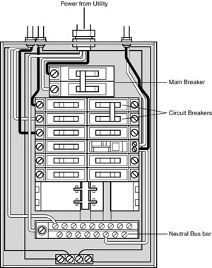
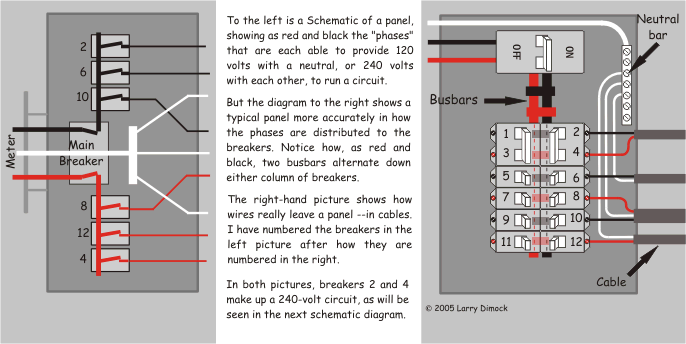
Residential Electrical Panel Diagram Iot Wiring Diagram A home electrical system is a complex network that distributes power throughout your house. at its core, electricity enters your home through the main service panel, where it’s divided into circuits that power different areas and appliances. these circuits are protected by circuit breakers or fuses, which prevent overloads and short circuits. First and foremost, it’s important to understand the fundamental components of a residential electrical wiring diagram. these diagrams depict the layout of electrical circuits, outlets, switches, and other electrical devices in your home. by using symbols and colors to represent various elements, these diagrams provide a visual representation. Key takeaways: – the main breaker and service disconnect are essential components of a 200 amp square d panel wiring diagram. – the main breaker acts as a master switch, allowing you to turn off the power to the entire panel. – the service disconnect is used to disconnect power from the main electrical service to the panel. The kitchen electric range may also be found to have a 3 wire or 4 wire cord or 220 volt outlet which will require proper electrical connections and wiring as found in the diagrams and instructions. most arc welders require a dedicated electrical circuit and 220 volt outlet that is sized according to the specifications of the welder as.

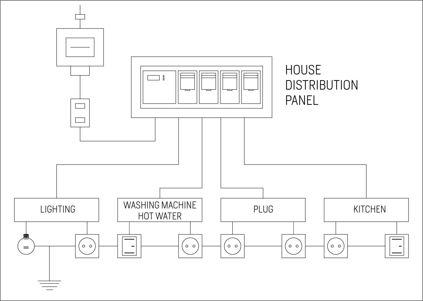
Simple Residential Wiring Diagram Iot Wiring Diagram Key takeaways: – the main breaker and service disconnect are essential components of a 200 amp square d panel wiring diagram. – the main breaker acts as a master switch, allowing you to turn off the power to the entire panel. – the service disconnect is used to disconnect power from the main electrical service to the panel. The kitchen electric range may also be found to have a 3 wire or 4 wire cord or 220 volt outlet which will require proper electrical connections and wiring as found in the diagrams and instructions. most arc welders require a dedicated electrical circuit and 220 volt outlet that is sized according to the specifications of the welder as. Electrical wiring serves as the system that enables electricity to move from the main power source to the outlets, fixtures, and appliances located within a building. it consists of conductors, cables, and devices carefully arranged to ensure the safe and efficient distribution of electrical power. proper design and installation are crucial for. A wiring diagram is a simplified representation of the conductors (wires) and components (devices, lights, motors, switches, sensors and more) that make up an electrical circuit or electrical system. some wiring diagrams show the exact wire connections that must be made for the system to work, while others offer a graphical representation of.

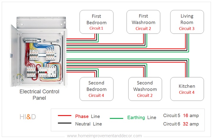
Electrical Wiring Layout Plan Iot Wiring Diagram Electrical wiring serves as the system that enables electricity to move from the main power source to the outlets, fixtures, and appliances located within a building. it consists of conductors, cables, and devices carefully arranged to ensure the safe and efficient distribution of electrical power. proper design and installation are crucial for. A wiring diagram is a simplified representation of the conductors (wires) and components (devices, lights, motors, switches, sensors and more) that make up an electrical circuit or electrical system. some wiring diagrams show the exact wire connections that must be made for the system to work, while others offer a graphical representation of.

Comments are closed.