Reference Symbol In Drawing

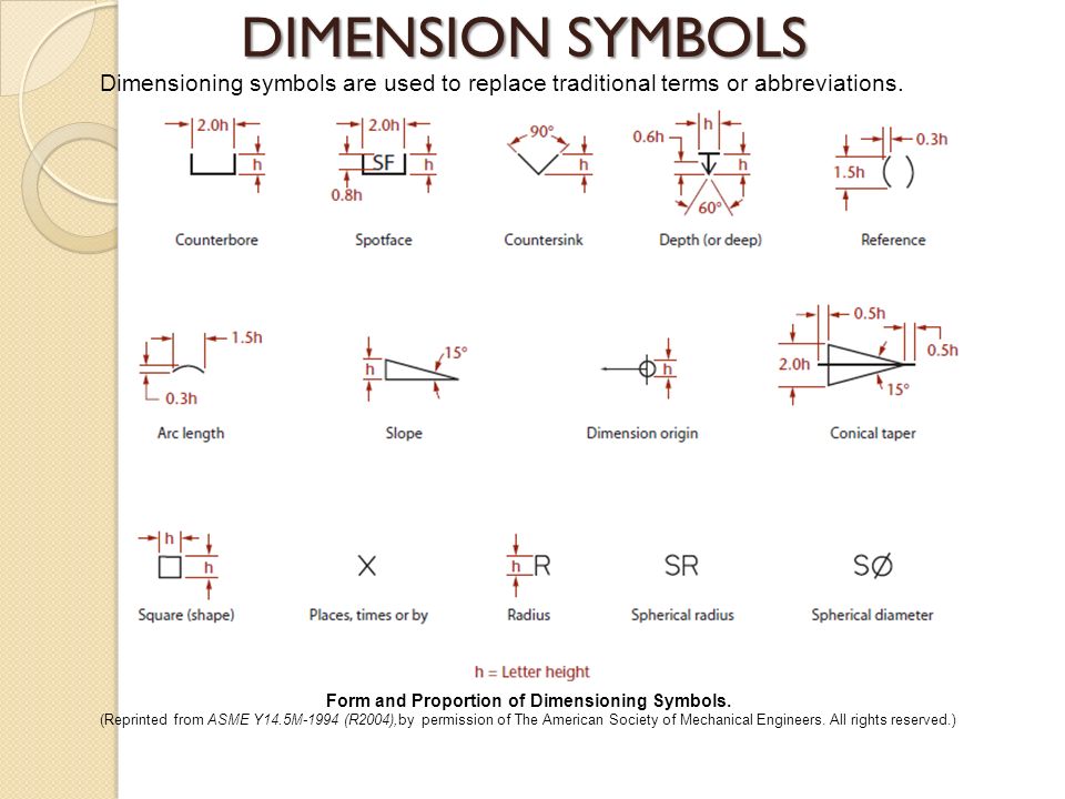
Reference Dimension Symbol There is no gd&t symbol for a reference dimension. reference dimensions are shown on a drawing as a value enclosed in parentheses. an alternate method is to follow the dimension with “reference” or “ref”. the use of “ref” or enclosing the dimension inside parentheses are by far the most common notations used. Geometric dimensioning and tolerancing symbols you can either create your own library of gd&t symbols, or use one of autocad’s gd&t fonts to insert the symbols as text. the following tables show how to construct the symbols. any needed height h 2 h h 2 h 60° 2 h identification letter datum feature symbol datum target symbol target point and.

Wallet Sized Gd T Symbol Reference Card Omnia Mfg Engineering A good design drawing can indicate all the details needed to produce a mechanical cnc milling part in an easy way. because there is no large space on a drawing to contain all the text to illustrate the image, abbreviations, and symbols are often used in engineering drawings to communicate the characteristics of the product to be manufactured. Gd&t flatness is a common symbol that references how flat a surface is regardless of any other datum’s or features. it comes in useful if a feature is to be defined on a drawing that needs to be uniformly flat without tightening any other dimensions on the drawing. the flatness tolerance references two parallel planes (parallel to the surface. To read and interpret engineering drawings effectively, start by examining the title block for important contextual information. familiarize yourself with the purpose, part number, material, finish, and other details provided. next, visualize the assembly in 3d, using isometric views provided in the drawing as a guide. For reference, every set of architectural drawings includes a symbol legend. if you aren’t familiar with a symbol, you will be able to find it in the legend. floor plan notes give additional context for the building. for instance, the notes can clarify exactly to what point on a wall dimensions should be measured.

Architectural Drawings 114 Cad Symbols Annotated Architizer Journal To read and interpret engineering drawings effectively, start by examining the title block for important contextual information. familiarize yourself with the purpose, part number, material, finish, and other details provided. next, visualize the assembly in 3d, using isometric views provided in the drawing as a guide. For reference, every set of architectural drawings includes a symbol legend. if you aren’t familiar with a symbol, you will be able to find it in the legend. floor plan notes give additional context for the building. for instance, the notes can clarify exactly to what point on a wall dimensions should be measured. Cross reference other symbols based on the type of object. more complex mechanical objects include additional symbols related to the specific type of machine the drawing depicts. depending on your specialty and the reason you're reading engineering drawings, you may not encounter any of these. A reference dimension is a repeat of a dimension or is derived from other values on the drawing or related drawings. regardless of material boundary (rmb) this is the condition where the stated tolerance limits must be met irrespective of as built datum feature size or location.

Gd T Symbols Reference Guide From Sigmetrix Mechanical Design Cross reference other symbols based on the type of object. more complex mechanical objects include additional symbols related to the specific type of machine the drawing depicts. depending on your specialty and the reason you're reading engineering drawings, you may not encounter any of these. A reference dimension is a repeat of a dimension or is derived from other values on the drawing or related drawings. regardless of material boundary (rmb) this is the condition where the stated tolerance limits must be met irrespective of as built datum feature size or location.

Comments are closed.