Rectification Circuit Diagram

Center Tapped Full Wave Rectifier Circuit Diagram Rectification is the conversion of alternating current (ac) to direct current (dc). a half wave rectifier is a circuit that allows only one half cycle of the ac voltage waveform to be applied to the load, resulting in one non alternating polarity across it. the resulting dc delivered to the load “pulsates” significantly. 3.2.1: half wave rectification. to understand the operation of a single diode in an ac circuit, consider the diagram of figure \(\pageindex{1}\). this is a simple series loop consisting of a sine wave source, a diode and a resistor that serves as the load.

Rectification Explained Electronics For Novices Full wave rectification is the process of converting an ac signal to a dc signal. rectifiers are circuits that convert alternating current (ac) to direct current (dc). full wave rectifiers specifically convert both the positive and negative half cycles of an ac waveform. full wave rectifiers achieve this by using a group of diodes. Rectifiers circuits. it plays a vital role in dc power supplies for converting ac signal into dc signal. p n junction diode have lot of applications and rectifier circuits are one of them. in simple words the electronic circuit which performs rectification is called rectifier circuit. by using this circuit we can able to convert electrical signals. An introduction to rectifier circuits. june 27, 2016 by donald krambeck. an important application of the diode is one that takes place in the design of the rectifier circuit. simply put, this circuit converts alternating current (ac) to direct current (dc). this is an essential circuit in ac to dc power supply design. The main advantages of a full wave bridge rectifier is that it has a smaller ac ripple value for a given load and a smaller reservoir or smoothing capacitor than an equivalent half wave rectifier. therefore, the fundamental frequency of the ripple voltage is twice that of the ac supply frequency (100hz) where for the half wave rectifier it is.

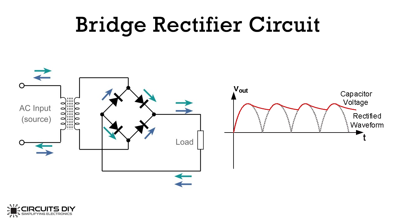
Simple Bridge Rectifier Circuit An introduction to rectifier circuits. june 27, 2016 by donald krambeck. an important application of the diode is one that takes place in the design of the rectifier circuit. simply put, this circuit converts alternating current (ac) to direct current (dc). this is an essential circuit in ac to dc power supply design. The main advantages of a full wave bridge rectifier is that it has a smaller ac ripple value for a given load and a smaller reservoir or smoothing capacitor than an equivalent half wave rectifier. therefore, the fundamental frequency of the ripple voltage is twice that of the ac supply frequency (100hz) where for the half wave rectifier it is. The circuit diagrams and waveforms we have given below will help you understand the operation of a bridge rectifier perfectly. in the circuit diagram, 4 diodes are arranged in the form of a bridge. the transformer secondary is connected to two diametrically opposite points of the bridge at points a & c. the load resistance r l is connected to. The solution to this problem is a full wave rectifier, which lets the positive half cycle flow and converts the negative half cycles into positives. in the devices you use, full wave rectifiers are what are most commonly used to convert ac voltage to dc voltage. a full wave rectifier circuit made with diodes is called a diode bridge.

Comments are closed.