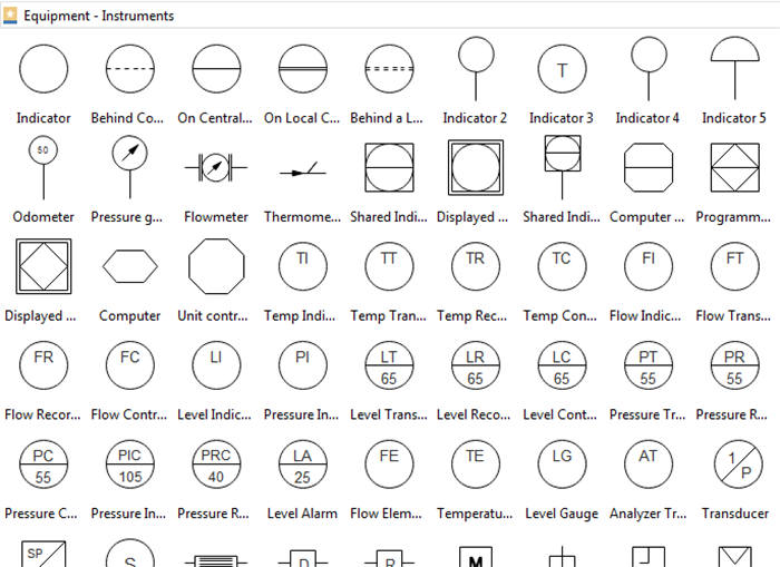
Piping Instrumentation Diagrams P Id How To Read P Id Symbols

How To Read P Id Piping And Instrumentation Diagram Process A p&id or process and instrumentation diagram provides a detailed graphical representation of the actual process system that includes the piping, equipment, valves, instrumentation, and other process components in the system. all components are represented using various p&id symbols. A piping & instrumentation diagram (p&id) is a detailed diagram used in the process industry to represent the piping, instrumentation, and control components of a physical process flow. p&ids are essential for visualizing the layout and interaction of process equipment and the instrumentation used to control the process.

How To Read A P Id Piping Instrumentation Diagram Youtube Here are some common categories and examples of p&id symbols: 1. piping p&id symbols. lines: solid lines for process pipes, dashed lines for instrument signals, etc. valves: gate valve, globe valve, check valve, ball valve, butterfly valve, etc. 2. Reading p&id is difficult for those who start their careers in oil &gas and similar chemical process industries. here, i have tried to explain p&id and pefs in an easy way. the piping and instrumentation diagram is also known as the process engineering flow scheme, pefs. you will learn how to read p&id and pefs with the help of the actual plant. Piping and instrumentation diagrams (p&ids) use specific symbols to show the connectivity of equipment, sensors, and valves in a control system. these symbols can represent actuators, sensors, and controllers and may be apparent in most, if not all, system diagrams. p&ids provide more detail than a process flow diagram with the exception of the. A piping and instrumentation diagram, also called p&id, is a diagram used to show a graphical display of a complete system. it includes all piping, instruments, valves, and equipment the system consists of. through a p&id, you can get the following information:.

How To Read A P Id Piping And Instrumentation Diagram Youtube Piping and instrumentation diagrams (p&ids) use specific symbols to show the connectivity of equipment, sensors, and valves in a control system. these symbols can represent actuators, sensors, and controllers and may be apparent in most, if not all, system diagrams. p&ids provide more detail than a process flow diagram with the exception of the. A piping and instrumentation diagram, also called p&id, is a diagram used to show a graphical display of a complete system. it includes all piping, instruments, valves, and equipment the system consists of. through a p&id, you can get the following information:. Instrumentation detail varies with the degree of design complexity. simplified or conceptual designs are called process flow diagrams (pfds). a pfd shows fewer details than a p&id and is usually the first step in the design process–more of a bird’s eye view. more fully developed piping and instrumentation diagrams (p&ids) are shown in a p&id. A1. p&id symbols, which stand for piping and instrumentation diagram symbols, are graphical representations used in engineering and process industries to depict the process flow, equipment, instrumentation, and control systems of a system or a plant. these symbols are essential for engineers, operators, and maintenance personnel to understand.

How To Read Piping And Instrumentation Diagram P Id Edrawmax Instrumentation detail varies with the degree of design complexity. simplified or conceptual designs are called process flow diagrams (pfds). a pfd shows fewer details than a p&id and is usually the first step in the design process–more of a bird’s eye view. more fully developed piping and instrumentation diagrams (p&ids) are shown in a p&id. A1. p&id symbols, which stand for piping and instrumentation diagram symbols, are graphical representations used in engineering and process industries to depict the process flow, equipment, instrumentation, and control systems of a system or a plant. these symbols are essential for engineers, operators, and maintenance personnel to understand.

P Id Diagram How To Read P Id Drawing Easily Piping

How To Read And Interpret Piping And Instrumentation Diagrams P Id

Comments are closed.