Piping Instrumentation Diagram Pdf

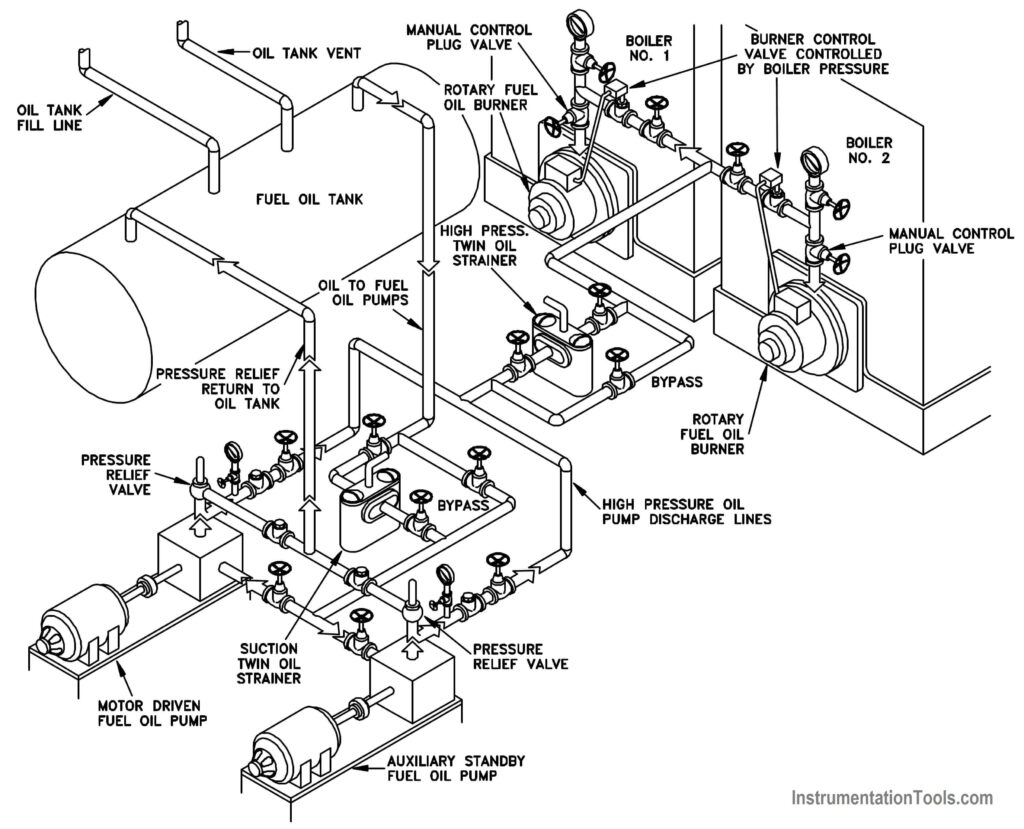
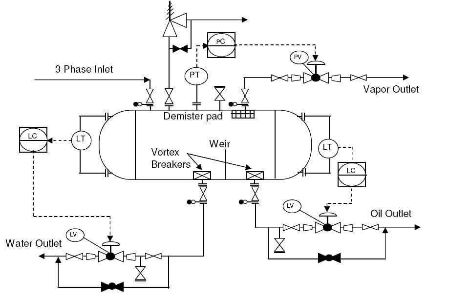
Piping Instrumentation Diagram Symbols Pdf At Samuel Landry Blog Compressor reciprocating compressor reciprocating compressor 2 compressor silencers centrifugal rotary compressor rotary compressor 2 rotory compressor. Piping and instrumentation diagrams (p&ids) are drawings showing piping and communications as schematic (unscaled) lines and control features as symbols. p&ids illustrate the functional relationship of piping, instrumentation, equipment, and controllers. they are usually located in the instrumentation drawings in a project drawing set.

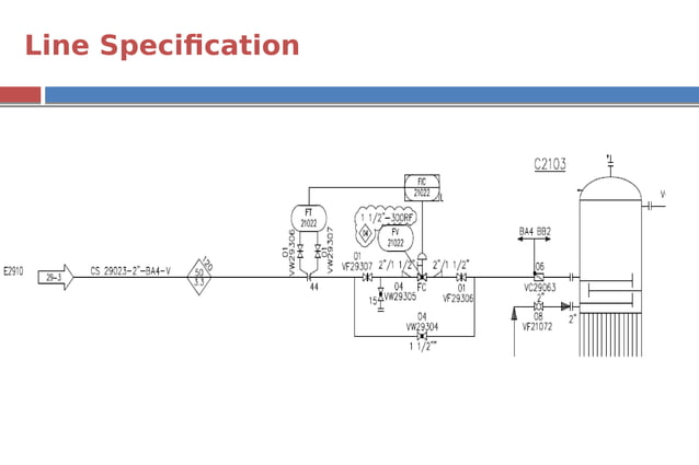
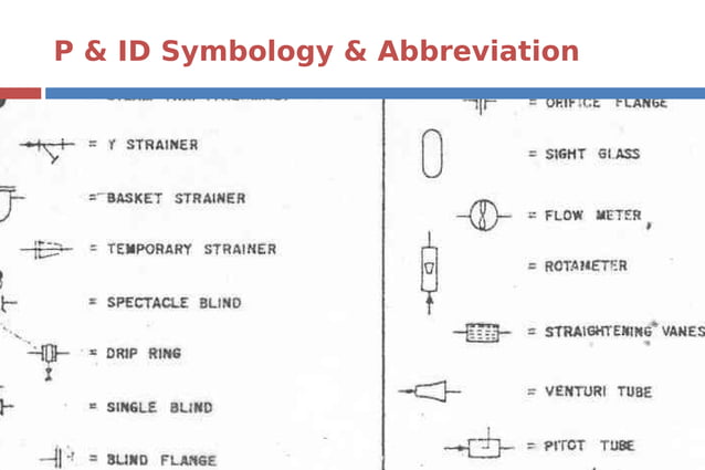
Piping Instrumentation Diagram Pdf Some instrument designations. p = pressure. i = indicator t= temperature c = controller f = flow. s = switch l = level. e = element t = transmitter g = gage. • isa designations usually used. Introduction. piping and instrumentation diagrams (p&ids) use specific symbols to show the connectivity of equipment, sensors, and valves in a control system. these symbols can represent actuators, sensors, and controllers and may be apparent in most, if not all, system diagrams. p&ids provide more detail than a process flow diagram with the. Instrument symbols. measured variable. p pressure. t temperature f flow l level. measured function. i indicator r recorder c controller. Piping and instrument diagram (p&id) is a schematic diagram that shows how equipment and instruments connect to form a functional process system. the p&id is the chief control document for the engineering design of petrochemical and refinery systems. defines scope. specifies systems. identifies essential components. guides engineering design.

Piping Instrumentation Diagram Pdf Instrument symbols. measured variable. p pressure. t temperature f flow l level. measured function. i indicator r recorder c controller. Piping and instrument diagram (p&id) is a schematic diagram that shows how equipment and instruments connect to form a functional process system. the p&id is the chief control document for the engineering design of petrochemical and refinery systems. defines scope. specifies systems. identifies essential components. guides engineering design. Piping and instrumentation diagram symbols pdf. a piping and instrumentation diagram (p&id) is a schematic representation of the process flow in a facility. it shows the piping, instrumentation, and control devices used in the process. p&id symbols are used to depict various components and equipment in the diagram. Instrumentation detail varies with the degree of design complexity. simplified or conceptual designs are called process flow diagrams (pfds). a pfd shows fewer details than a p&id and is usually the first step in the design process–more of a bird’s eye view. more fully developed piping and instrumentation diagrams (p&ids) are shown in a p&id.

What Is Piping And Instrumentation Diagram P Id Instrumentation Tools Piping and instrumentation diagram symbols pdf. a piping and instrumentation diagram (p&id) is a schematic representation of the process flow in a facility. it shows the piping, instrumentation, and control devices used in the process. p&id symbols are used to depict various components and equipment in the diagram. Instrumentation detail varies with the degree of design complexity. simplified or conceptual designs are called process flow diagrams (pfds). a pfd shows fewer details than a p&id and is usually the first step in the design process–more of a bird’s eye view. more fully developed piping and instrumentation diagrams (p&ids) are shown in a p&id.

Piping Instrumentation Diagram Pdf

Comments are closed.