Piping Instrument Diagram

What Is Piping And Instrumentation Diagram P Id Instrumentation Tools A piping and instrumentation diagram (p&id) is defined as follows: a diagram which shows the interconnection of process equipment and the instrumentation used to control the process. in the process industry, a standard set of symbols is used to prepare drawings of processes. the instrument symbols used in these drawings are generally based on. Instrumentation detail varies with the degree of design complexity. simplified or conceptual designs are called process flow diagrams (pfds). a pfd shows fewer details than a p&id and is usually the first step in the design process–more of a bird’s eye view. more fully developed piping and instrumentation diagrams (p&ids) are shown in a p&id.

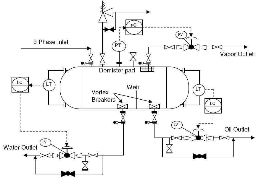
Piping Instrumentation Diagrams P Ids Punchlist Zero A p&id or process and instrumentation diagram provides a detailed graphical representation of the actual process system that includes the piping, equipment, valves, instrumentation, and other process components in the system. all components are represented using various p&id symbols. A piping and instrumentation diagram (p&id) is a comprehensive schematic that illustrates the functional relationship of piping, instrumentation, and system equipment components within a process plant. it serves as a vital tool in the process industry, forming the backbone of the design phase and providing a detailed layout of the plant's. A piping & instrumentation diagram (p&id) is a detailed diagram used in the process industry to represent the piping, instrumentation, and control components of a physical process flow. p&ids are essential for visualizing the layout and interaction of process equipment and the instrumentation used to control the process. Schematic illustration of a functional relationship between piping, instrumentation and system components. p&id's shows all piping including physical sequences of branches, reducers, valves, equipment, instrumentation and control interlocks. the p&id's are used to operate process systems. p&id diagram online drawing tool. a p&id should include:.

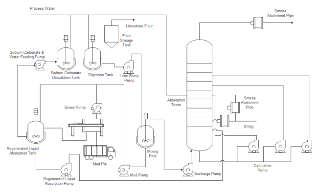
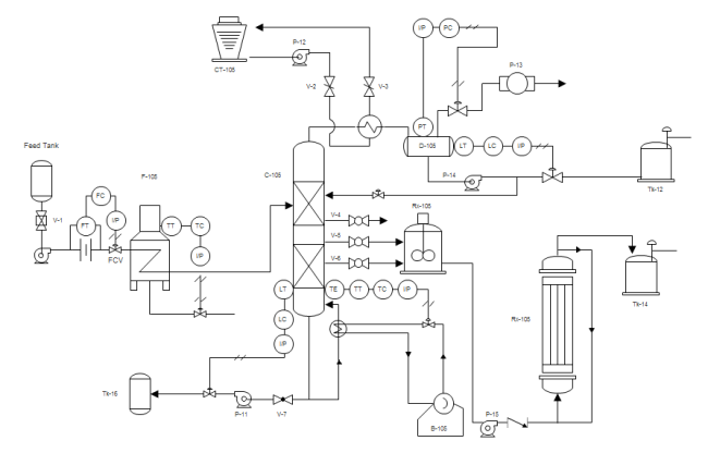
What Is A Piping And Instrumentation Diagram P Id Edrawmax A piping & instrumentation diagram (p&id) is a detailed diagram used in the process industry to represent the piping, instrumentation, and control components of a physical process flow. p&ids are essential for visualizing the layout and interaction of process equipment and the instrumentation used to control the process. Schematic illustration of a functional relationship between piping, instrumentation and system components. p&id's shows all piping including physical sequences of branches, reducers, valves, equipment, instrumentation and control interlocks. the p&id's are used to operate process systems. p&id diagram online drawing tool. a p&id should include:. A piping & instrumentation diagram (p&id) is a schematic layout of a plant that displays the units to be used, the pipes connecting these units, and the sensors and control valves. standard structures located on a p&id include storage tanks, surge tanks, pumps, heat exchangers, reactors, and distillation columns. The piping and instrumentation diagram (p&id) is a graphical representation of the actual process plant using various symbols that represent actual equipment. it is a detailed diagram in the process industry that shows all piping including physical sequences of branches, reducers, valves, equipment, instrumentation and control interlocks.

How To Read Piping And Instrumentation Diagram A piping & instrumentation diagram (p&id) is a schematic layout of a plant that displays the units to be used, the pipes connecting these units, and the sensors and control valves. standard structures located on a p&id include storage tanks, surge tanks, pumps, heat exchangers, reactors, and distillation columns. The piping and instrumentation diagram (p&id) is a graphical representation of the actual process plant using various symbols that represent actual equipment. it is a detailed diagram in the process industry that shows all piping including physical sequences of branches, reducers, valves, equipment, instrumentation and control interlocks.

Comments are closed.