P Id Piping Instrumentation Diagram

How To Read A P Id Piping Instrumentation Diagram Youtube Instrumentation detail varies with the degree of design complexity. simplified or conceptual designs are called process flow diagrams (pfds). a pfd shows fewer details than a p&id and is usually the first step in the design process–more of a bird’s eye view. more fully developed piping and instrumentation diagrams (p&ids) are shown in a p&id. P&id's shows all piping including physical sequences of branches, reducers, valves, equipment, instrumentation and control interlocks. the p&id's are used to operate process systems. p&id diagram online drawing tool. a p&id should include: instrumentation and designations. mechanical equipment with names and numbers.

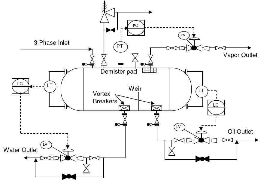
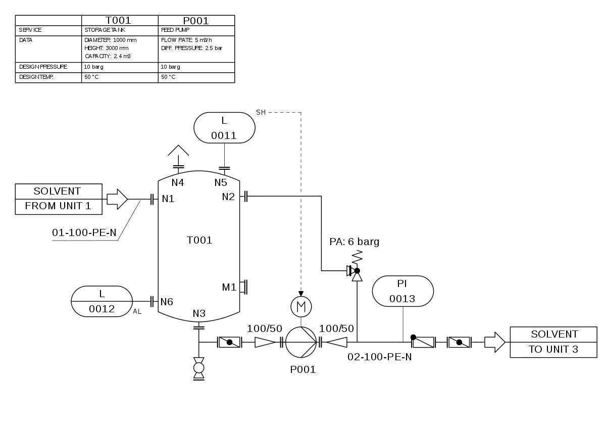
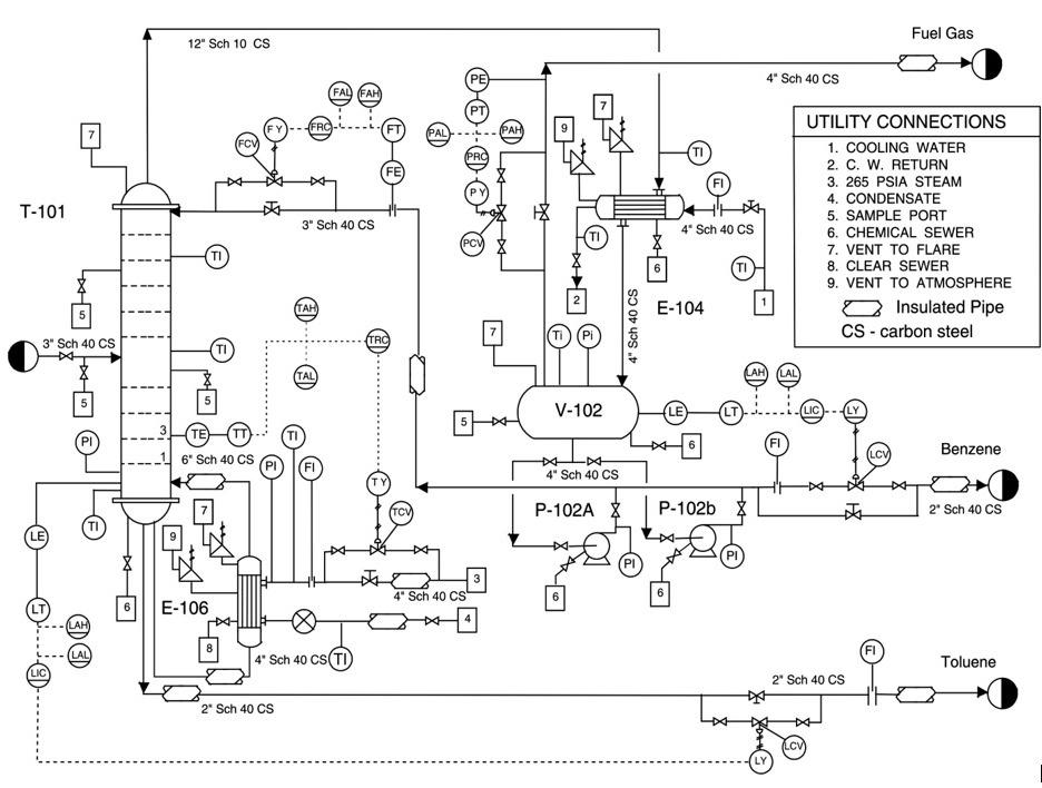
What Is Piping And Instrumentation Diagram P Id Inst Tools A piping and instrumentation diagram (p&id) is defined as follows: a diagram which shows the interconnection of process equipment and the instrumentation used to control the process. in the process industry, a standard set of symbols is used to prepare drawings of processes. the instrument symbols used in these drawings are generally based on. A p&id or process and instrumentation diagram provides a detailed graphical representation of the actual process system that includes the piping, equipment, valves, instrumentation, and other process components in the system. all components are represented using various p&id symbols. A piping & instrumentation diagram (p&id) is a detailed diagram used in the process industry to represent the piping, instrumentation, and control components of a physical process flow. p&ids are essential for visualizing the layout and interaction of process equipment and the instrumentation used to control the process. The basics of p&id understanding the essence. a piping and instrumentation diagram (p&id) is a schematic representation that illustrates the relationships between various equipment, piping, instrumentation, and controls in a process system. it provides a clear visual overview of the process flow and the components involved. components of a p&id.

How To Read And Interpret Piping And Instrumentation Diagrams P Id A piping & instrumentation diagram (p&id) is a detailed diagram used in the process industry to represent the piping, instrumentation, and control components of a physical process flow. p&ids are essential for visualizing the layout and interaction of process equipment and the instrumentation used to control the process. The basics of p&id understanding the essence. a piping and instrumentation diagram (p&id) is a schematic representation that illustrates the relationships between various equipment, piping, instrumentation, and controls in a process system. it provides a clear visual overview of the process flow and the components involved. components of a p&id. A piping and instrumentation diagram (p&id) is a comprehensive schematic that illustrates the functional relationship of piping, instrumentation, and system equipment components within a process plant. it serves as a vital tool in the process industry, forming the backbone of the design phase and providing a detailed layout of the plant's process. Piping and instrumentation diagrams (p&ids) use specific symbols to show the connectivity of equipment, sensors, and valves in a control system. these symbols can represent actuators, sensors, and controllers and may be apparent in most, if not all, system diagrams. p&ids provide more detail than a process flow diagram with the exception of the.

Piping Instrumentation Diagrams P Ids Punchlist Zero A piping and instrumentation diagram (p&id) is a comprehensive schematic that illustrates the functional relationship of piping, instrumentation, and system equipment components within a process plant. it serves as a vital tool in the process industry, forming the backbone of the design phase and providing a detailed layout of the plant's process. Piping and instrumentation diagrams (p&ids) use specific symbols to show the connectivity of equipment, sensors, and valves in a control system. these symbols can represent actuators, sensors, and controllers and may be apparent in most, if not all, system diagrams. p&ids provide more detail than a process flow diagram with the exception of the.

P Id Piping Instrumentation Diagram

Solved Consider The Piping And Instrumentation Diagram Chegg

Comments are closed.