Marine Alternator Wiring Schematic

Marine Alternator Wiring Diagram Many alternators require ignition voltage to initiate charging. you must verify that all required connections are connected to the proper terminal and have the correct voltage in order for the alternator to operate properly. below you will find the most common alternator circuits used on marine applications. alternator circuits. Here is a summary of the steps involved in wiring a boat alternator: gather the necessary tools and materials. before you begin, make sure you have all the required tools and materials, including wire, connectors, crimping tool, electrical tape, and a wiring diagram for your specific alternator. disconnect the battery.

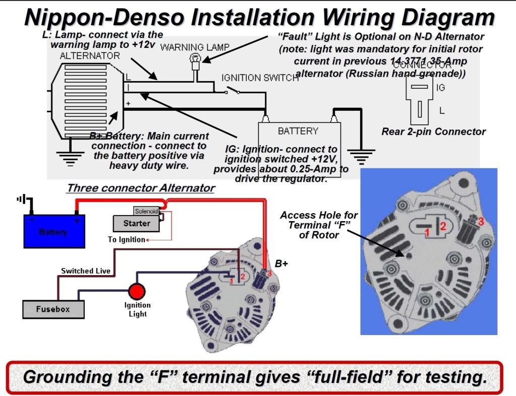
Marine Alternator Wiring Schematic A marine alternator wiring diagram is a schematic representation of the electrical connections and components in a marine alternator system. it provides a visual guide for installing and troubleshooting the wiring for the alternator, ensuring proper functionality and safety of the system. this diagram is invaluable for boat owners and marine technicians who need to understand and work with the. The ig or r contact is a switched wire from the ignition switch. the wire supplies voltage directly to the alternator regulator so that it always receives voltage to switch on. simple l and ig connection with t connector. code b , a or 30: output voltage. an output voltage and current goes from the alternator to the battery. The alternator is responsible for converting mechanical energy from the engine into electrical energy to charge the battery and power the boat’s electrical system. it is important to follow the correct wiring diagram to ensure the alternator is connected properly and functions effectively. step 1: disconnect the battery. A marine alternator wiring diagram is a simplified schematic representation of an electrical system found on a boat. it shows the layout of the various components in the system, including the alternator, batteries, switches, and other related items. by studying the diagram, you can trace the flow of electricity from the alternator to the.

Marine Alternator Wiring Diagram Inspiration Delco Of 2 Natebird Me The alternator is responsible for converting mechanical energy from the engine into electrical energy to charge the battery and power the boat’s electrical system. it is important to follow the correct wiring diagram to ensure the alternator is connected properly and functions effectively. step 1: disconnect the battery. A marine alternator wiring diagram is a simplified schematic representation of an electrical system found on a boat. it shows the layout of the various components in the system, including the alternator, batteries, switches, and other related items. by studying the diagram, you can trace the flow of electricity from the alternator to the. The sae j1171 marine alternator wiring diagram includes a number of components that must be connected correctly in order for the system to work properly. this includes the alternator, battery, switches, fuses, and relays. in addition, the diagram also shows how to connect the alternator to the boat's power source, such as a generator or shore. Identify the wires: take a good look at the alternator and identify the different wires. this may include the main power wire, ignition wire, ground wire, and any additional wires specific to your alternator model. 3. check the wiring diagram: a wiring diagram is a valuable tool that will show you how to correctly connect the wires.

Comments are closed.