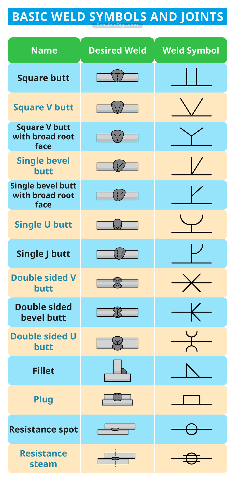
Introduction To Welding Symbols

Welding Symbols Diagrams Types Fully Explained Sensible Digs For instance. (example 1) indication: weld height is 3, staggered welding, weld seam length is 50, interval is 30, site welding is required. example 2: statement: spot weld diameter is 5, the number of spot welds is 10, and the interval is 30. example 3: indication: the weld height is 3, with full welding around. The 9 steps below represent a very basic introduction to welding symbols. this is just barely skimming the surface of weld symbols training. if you have a questions please let us know by replying to the post. welding symbols basics. every weld symbol must consist of an arrow and a reference line. the arrow may point up or down.

Welding Symbols Diagrams Types Fully Explained Sensible Digs This information is often communicated via the blueprint. welding can require a lot of specific information, for example: the type and size of the weld, the required weld groove preparation, the extent and location of the weld. welding symbols provide a space saving method for conveying all this, and more, information. Weld symbols are a key part of welding documentation, and understanding how to read weld symbols is critical for welders. there are three main elements to a weld symbol: tail. the reference line is a horizontal line that is used to align the other elements of the symbol. the arrow is used to point to the location of the weld, and the tail. A welding symbol is what you see above and contains the arrow, reference line, and tail. you can remove the tail if there’s no information needed in it. you place a weld symbol on the reference line of a welding symbol to indicate what type of weld you require. 1. reference line. This video explains what weld symbols are, and how to identify their meaning when drawn on a reference line. examples are given to reinforce concepts related.

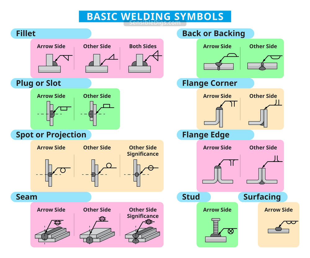
Weld Symbols Blueprints Introduction To Welding Symbols Welding A welding symbol is what you see above and contains the arrow, reference line, and tail. you can remove the tail if there’s no information needed in it. you place a weld symbol on the reference line of a welding symbol to indicate what type of weld you require. 1. reference line. This video explains what weld symbols are, and how to identify their meaning when drawn on a reference line. examples are given to reinforce concepts related. Spacer – this symbol indicates the type and the dimension of the spacer that is inserted between the welded pieces. weld all around – it signals that the weld is to be made over the entire circumference. flag symbol – field weld made on site. contour – these symbols designate the final weld end product contour. Projection welding symbol. seam welding symbol. back or backing welding symbol. surfacing welding symbol. edge welding symbol. some of these most commonly used basic welding symbols are explained here: 1. fillet weld symbol. a fillet weld is used to join two pieces of metal at a right angle.

Welding Symbols With Figures Paktechpoint Spacer – this symbol indicates the type and the dimension of the spacer that is inserted between the welded pieces. weld all around – it signals that the weld is to be made over the entire circumference. flag symbol – field weld made on site. contour – these symbols designate the final weld end product contour. Projection welding symbol. seam welding symbol. back or backing welding symbol. surfacing welding symbol. edge welding symbol. some of these most commonly used basic welding symbols are explained here: 1. fillet weld symbol. a fillet weld is used to join two pieces of metal at a right angle.

Understanding The Basic Welding Symbols

Introduction To Welding Symbols Youtube

Comments are closed.