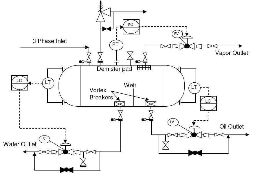
Interpreting Piping Instrumentation Diagram P Id In English

Interpreting Piping Instrumentation Diagram P Id In English Here, i have tried to explain p&id and pefs in an easy way. the piping and instrumentation diagram is also known as the process engineering flow scheme, pefs. you will learn how to read p&id and pefs with the help of the actual plant drawing. p&id is more complex than pfd and includes lots of details. This video talks about what is piping and instrumentation diagram, and how to read p &id drawing. if you have any questions about this video, do ask me in t.

What Is Piping And Instrumentation Diagram P Id Instrumentation Tools Instrumentation detail varies with the degree of design complexity. simplified or conceptual designs are called process flow diagrams (pfds). a pfd shows fewer details than a p&id and is usually the first step in the design process–more of a bird’s eye view. more fully developed piping and instrumentation diagrams (p&ids) are shown in a p&id. To read our blog on this topic, pls visit our website: instrumentationacademy p id how to read pid drawing easily piping instrumentation diagr. A piping and instrumentation diagram, also called p&id, is a diagram used to show a graphical display of a complete system. it includes all piping, instruments, valves, and equipment the system consists of. through a p&id, you can get the following information:. A piping and instrumentation diagram (p&id) is a comprehensive schematic that illustrates the functional relationship of piping, instrumentation, and system equipment components within a process plant. it serves as a vital tool in the process industry, forming the backbone of the design phase and providing a detailed layout of the plant's process.

How To Read And Interpret Piping And Instrumentation Diagrams P Id A piping and instrumentation diagram, also called p&id, is a diagram used to show a graphical display of a complete system. it includes all piping, instruments, valves, and equipment the system consists of. through a p&id, you can get the following information:. A piping and instrumentation diagram (p&id) is a comprehensive schematic that illustrates the functional relationship of piping, instrumentation, and system equipment components within a process plant. it serves as a vital tool in the process industry, forming the backbone of the design phase and providing a detailed layout of the plant's process. A p&id drawing serves as a guide for start up and operational data. it is the basic training document to explain the process details to operation guys, field engineers, and maintenance professionals. the p&id drawings help them to track the interconnection between the piping and instrumentation and equipment. How to read p&ids correctly. part 1. in this article, you’ll learn what piping and instrumentation diagrams are and how to read them correctly. after exploring lots of videos and articles about p&ids we concluded that reading the valve symbols, lines, codes, etc. one by one and memorizing them, is the most tedious and wrong method of learning.

Comments are closed.