Identify Instruments In Piping And Instrumentation Diagram

Identify Instruments In Piping And Instrumentation Diagram Vii. piping & instrumentation diagram (p&id) standards and regulations. piping & instrumentation diagrams (p&ids) are governed by various standards and regulations to ensure consistency, safety, and clarity. these standards provide guidelines on symbols, notations, and best practices for creating p&ids. here are the primary standards and. Instrumentation detail varies with the degree of design complexity. simplified or conceptual designs are called process flow diagrams (pfds). a pfd shows fewer details than a p&id and is usually the first step in the design process–more of a bird’s eye view. more fully developed piping and instrumentation diagrams (p&ids) are shown in a p&id.

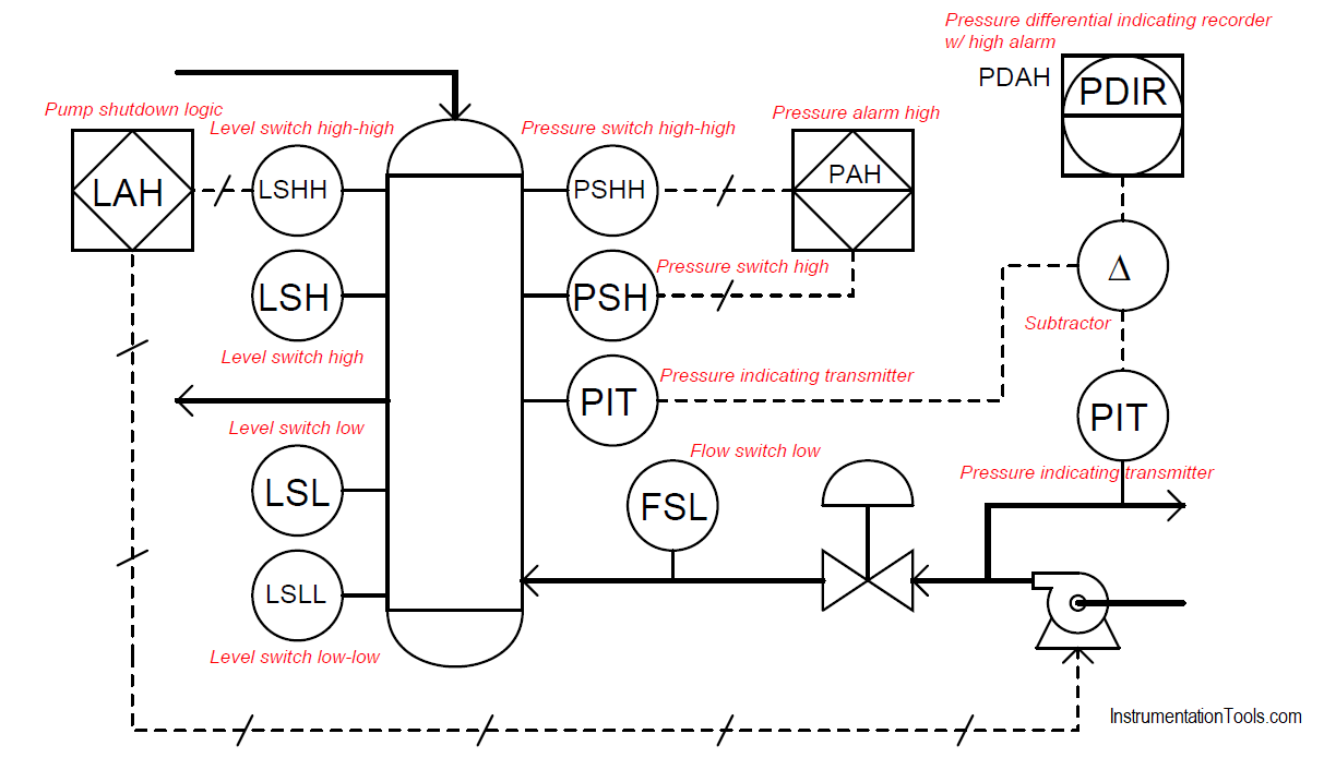
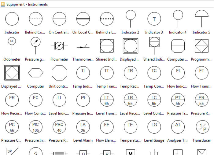
How To Read Piping And Instrumentation Diagram Piping and instrumentation diagrams (p&ids) use specific symbols to show the connectivity of equipment, sensors, and valves in a control system. these symbols can represent actuators, sensors, and controllers and may be apparent in most, if not all, system diagrams. p&ids provide more detail than a process flow diagram with the exception of the. A piping & instrumentation diagram (p&id) is a schematic layout of a plant that displays the units to be used, the pipes connecting these units, and the sensors and control valves. standard structures located on a p&id include storage tanks, surge tanks, pumps, heat exchangers, reactors, and distillation columns. A piping and instrumentation diagram (p&id) is a schematic representation that illustrates the relationships between various equipment, piping, instrumentation, and controls in a process system. it provides a clear visual overview of the process flow and the components involved. components of a p&id. a p&id comprises several essential components:. The piping and instrumentation diagram (p&id) contains additional information than the pfd. it includes both primary and secondary flows, control loops, and instrumentation. p&ids are mostly utilized by process technicians and engineers. in general, there is a distinct difference between pfds and p&ids:.

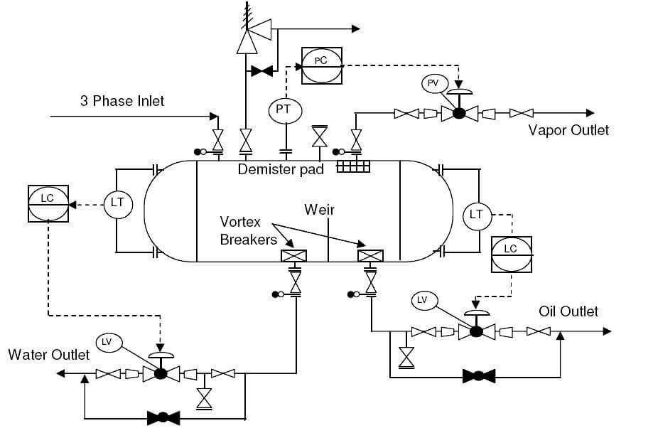
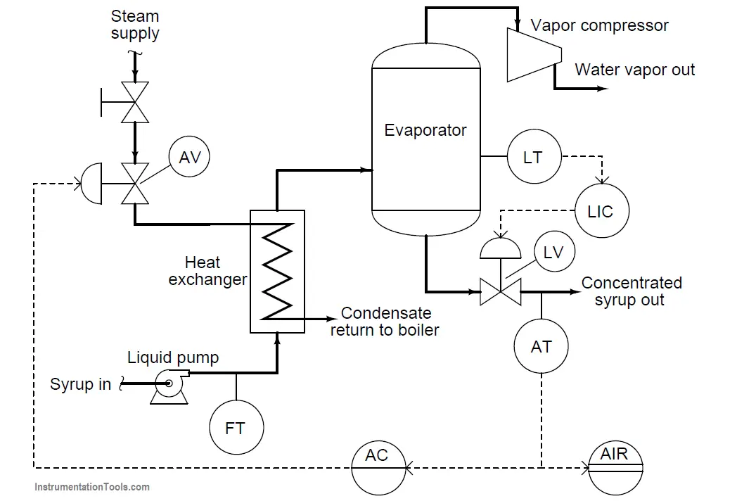
What Is Piping And Instrumentation Diagram P Id Inst Tools A piping and instrumentation diagram (p&id) is a schematic representation that illustrates the relationships between various equipment, piping, instrumentation, and controls in a process system. it provides a clear visual overview of the process flow and the components involved. components of a p&id. a p&id comprises several essential components:. The piping and instrumentation diagram (p&id) contains additional information than the pfd. it includes both primary and secondary flows, control loops, and instrumentation. p&ids are mostly utilized by process technicians and engineers. in general, there is a distinct difference between pfds and p&ids:. A piping and instrumentation diagram, also called p&id, is a diagram used to show a graphical display of a complete system. it includes all piping, instruments, valves, and equipment the system consists of. through a p&id, you can get the following information: the mechanical and electrical details of a given system or process, piping. The piping and instrumentation diagram (p&id) is a graphical representation of the actual process plant using various symbols that represent actual equipment. it is a detailed diagram in the process industry that shows all piping including physical sequences of branches, reducers, valves, equipment, instrumentation and control interlocks.

How To Read P Id Piping And Instrumentation Diagram Process A piping and instrumentation diagram, also called p&id, is a diagram used to show a graphical display of a complete system. it includes all piping, instruments, valves, and equipment the system consists of. through a p&id, you can get the following information: the mechanical and electrical details of a given system or process, piping. The piping and instrumentation diagram (p&id) is a graphical representation of the actual process plant using various symbols that represent actual equipment. it is a detailed diagram in the process industry that shows all piping including physical sequences of branches, reducers, valves, equipment, instrumentation and control interlocks.

Questions On Piping And Instrumentation Diagrams

How To Read And Interpret Piping And Instrumentation Diagrams P Id

Comments are closed.