How To Wire A Din Plug

How To Wire A Din Connector Showmecables 5 pin din male connector at keyboard stylewelcome to show me cables. today we’ll be taking a look at the commonly used and ofte. Showmecables 6 pin din male solder connectorwelcome to show me cables. today we’ll be taking a look at the commonly used and often confusing.
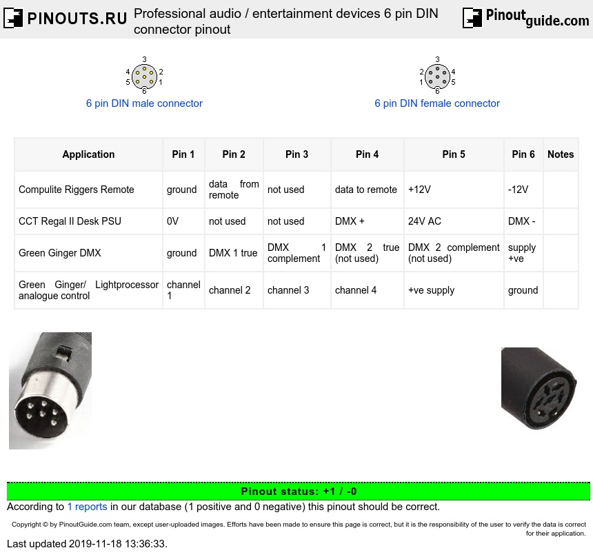
How To Wire A Din Plug Insert the wires: insert the stripped ends of the wires into the corresponding pin slots. for most din connectors, there are screw terminals for each pin. loosen the screws using the screwdriver to create a gap that allows inserting the wire. connect both poles on the connector to the power supply (the polarity is not important here). Five pin male 180° din connector from a 1988 schneider mf2 keyboard by cherry. the din connector is an electrical connector that was standardized by the deutsches institut für normung (din), the german institute for standards, in the mid 1950s, initially with 3 pins for mono, but when stereo connections and gear appeared in late 1950s (1959 or so), versions with 5 pins or more were launched. In this video our electrical engineer shows you how to wire and install a din plug properly. by doing it in this way you maintain the correct ip rating of th. Step 2: positioning the boot. most din connectors are sold disassembled. if this is not the case, separate the connector into individual parts. to start the installation, simply slide the outer protective layer (boot) of the cable over the bare wire.
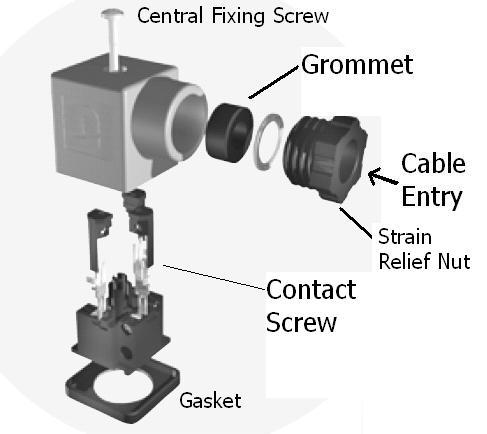
How To Wire A Din Connector In this video our electrical engineer shows you how to wire and install a din plug properly. by doing it in this way you maintain the correct ip rating of th. Step 2: positioning the boot. most din connectors are sold disassembled. if this is not the case, separate the connector into individual parts. to start the installation, simply slide the outer protective layer (boot) of the cable over the bare wire. Below are some of the various standards of din connectors. din 41524 – circular connectors commonly used for some digital signals or audio signals. din 41612 – rectangular connectors commonly used to connect plug in cards to a motherboard or backplane. din 41585 – for automotive coaxial connectors. din 41652 d – subminiature connectors. This versatile connector is widely used in a variety of applications, including audio, video, and data transmission. understanding the pinout and wiring diagram of the 8 pin din connector is crucial for properly connecting and utilizing this component. the 8 pin din connector features eight pins arranged in a circular pattern.
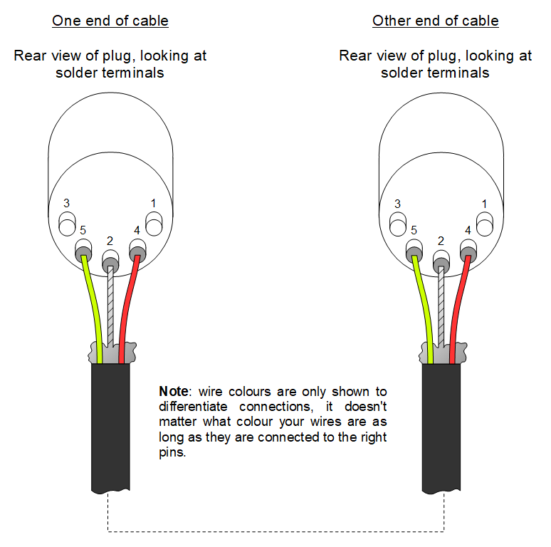
Wiring Diagram For 5 Pin Din Plug Wiring Diagram Below are some of the various standards of din connectors. din 41524 – circular connectors commonly used for some digital signals or audio signals. din 41612 – rectangular connectors commonly used to connect plug in cards to a motherboard or backplane. din 41585 – for automotive coaxial connectors. din 41652 d – subminiature connectors. This versatile connector is widely used in a variety of applications, including audio, video, and data transmission. understanding the pinout and wiring diagram of the 8 pin din connector is crucial for properly connecting and utilizing this component. the 8 pin din connector features eight pins arranged in a circular pattern.
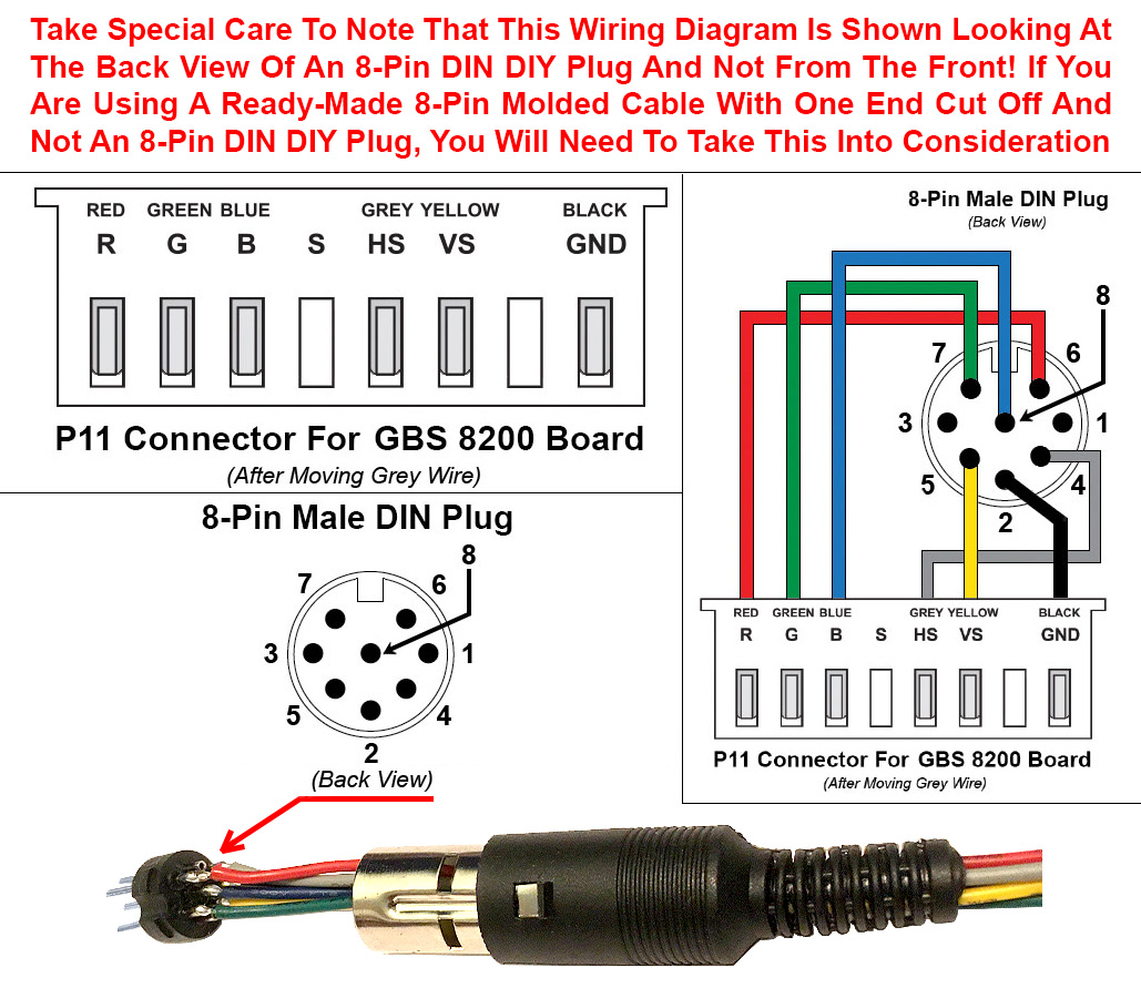
3 Pin Din Connector Wiring Diagram
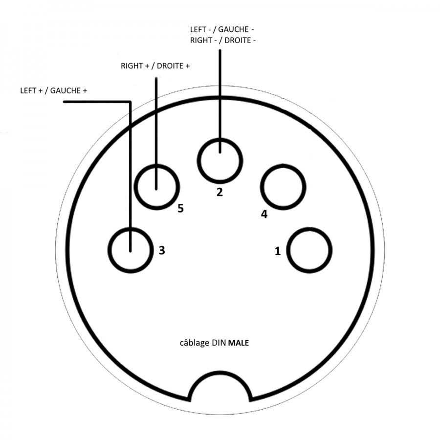
Din Wiring Diagrams

Comments are closed.