How To Read Electrical Schematic

How To Read A Schematic Sparkfun Learn An electrical schematic is a diagram that shows how all of the wires and components in an electronic circuit are connected. they’re like a map for building or troubleshooting circuits, and can tell you almost everything you need to know to understand how a circuit works. the ability to read electrical schematics is a really useful skill to have. Understanding how to read and follow schematics is an important skill for any electronics engineer. this tutorial should turn you into a fully literate schematic reader! we'll go over all of the fundamental schematic symbols: then we'll talk about how those symbols are connected on schematics to create a model of a circuit. we'll also go over a.

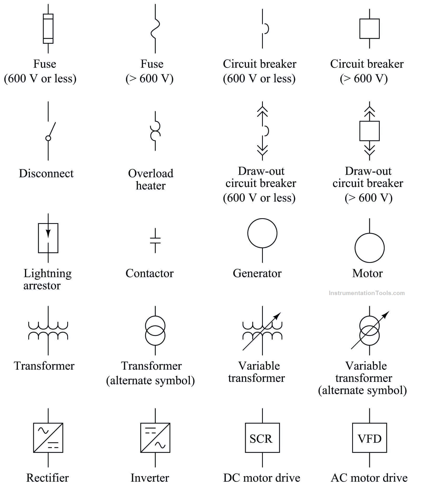
How To Read And Understand An Electrical Schematic An electrical schematic is a graphical representation of an electrical circuit. it shows the connections and components of the circuit in a clear and concise manner. understanding the key components of an electrical schematic is essential for anyone working with electrical systems. 1. symbols: one of the most important elements of an electrical. Anyone can take an idea this far, but the next step requires a fundamental understanding of circuit schematics. circuit schematics are the bridge between conceptual electrical design and physical realization of a printed circuit board assembly, or pcba. example circuit schematic: class a common base small signal high gain amplifier. Part 3: recognizing connection and lines in electrical schematics. understanding the representation of symbols and components is just the primary stage in reading electrical schematics. next, you need to identify how the symbols are connected and how to figure out their connections. 1. nets are lines that will show how components are connected. 2. Step 2: recognize major components. before you dive into the wires and connections, take a high level view of the major components included in the system. identify transformers, motors, solenoid valves, motor starters, lighting ballasts, microprocessors, switches, and other significant components by their symbols.

How To Read Electrical Wiring Diagrams Wiring Diagram And Schematics Part 3: recognizing connection and lines in electrical schematics. understanding the representation of symbols and components is just the primary stage in reading electrical schematics. next, you need to identify how the symbols are connected and how to figure out their connections. 1. nets are lines that will show how components are connected. 2. Step 2: recognize major components. before you dive into the wires and connections, take a high level view of the major components included in the system. identify transformers, motors, solenoid valves, motor starters, lighting ballasts, microprocessors, switches, and other significant components by their symbols. A schematic, also known as a circuit diagram, is a visual representation of an electronic circuit. it uses standardized symbols to represent electronic components and shows how these components are connected to form a circuit. unlike a pictorial diagram, a schematic doesn’t aim to represent the physical layout of the components. An electrical schematic is a graphical representation of an electrical circuit, using standardized symbols to depict components and their connections. schematics convey the circuit's design and function, making it easier to understand how it operates. symbols are the foundation of circuit diagrams, enabling engineers, electricians, and.

Comments are closed.