How To Read Continuous Cooling Transformation Diagram

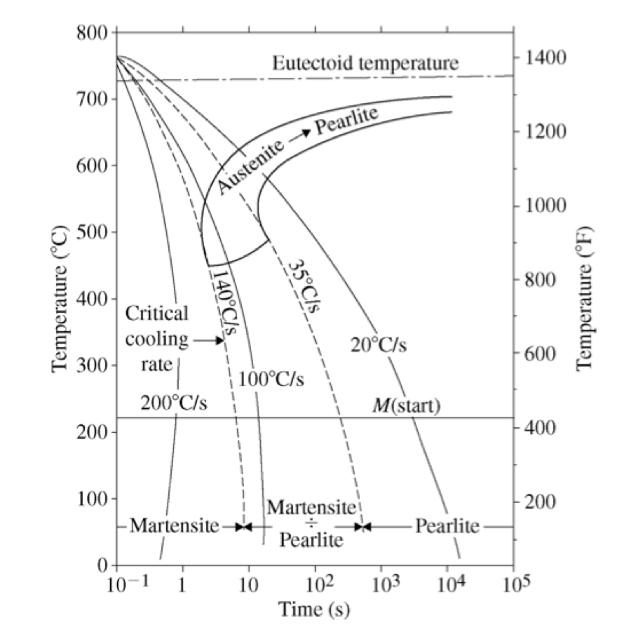
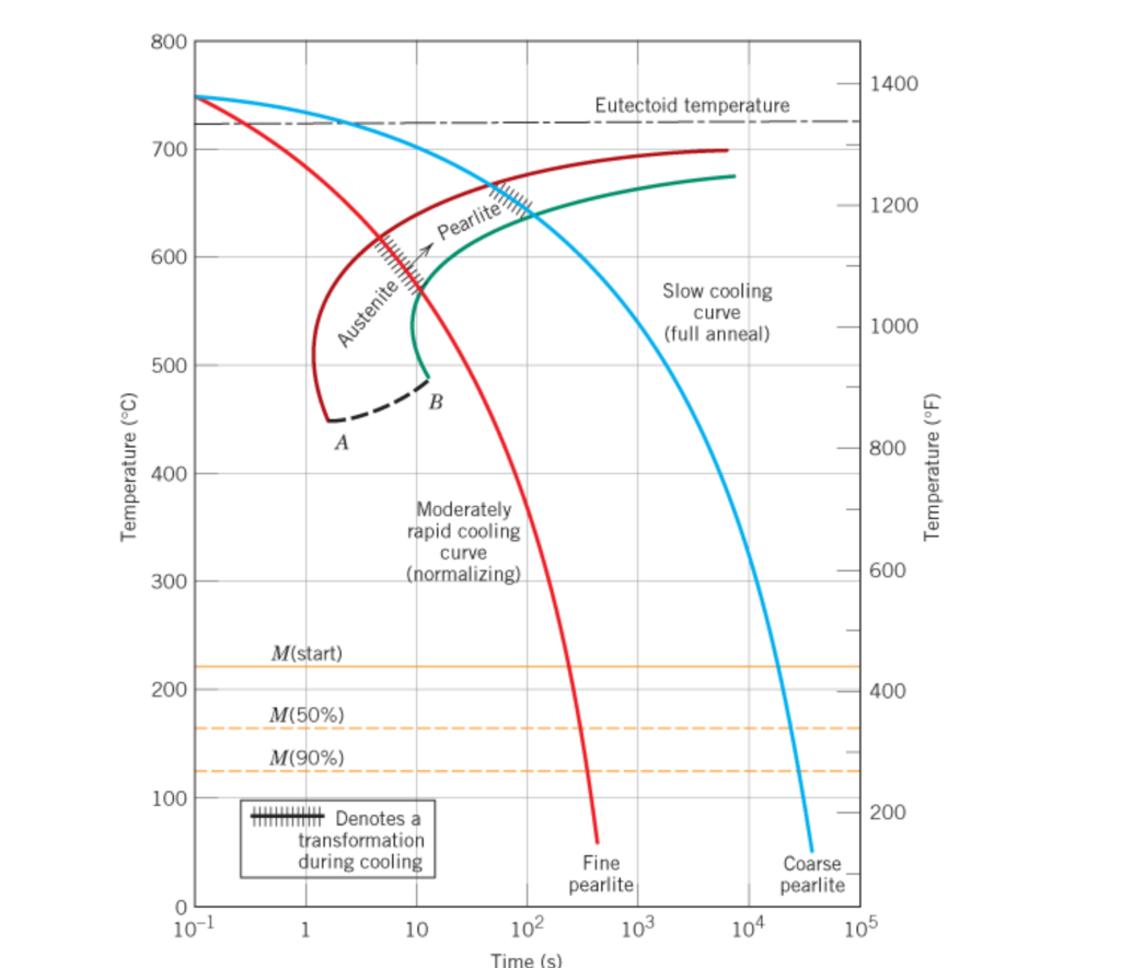
Continuous Cooling Transformation Diagram Definition: stability of phases during continuous cooling of austenite. there are two types of cct diagrams. i) plot of (for each type of transformation) transformation start, specific fraction of transformation and transformation finish temperature against transformation time on each cooling curve. There are two types of continuous cooling diagrams drawn for practical purposes. type 1: this is the plot beginning with the transformation start point, cooling with a specific transformation fraction and ending with a transformation finish temperature for all products against transformation time for each cooling curve. type 2: this is the plot.

Continuous Cooling Transformation Diagram Typical continuous cooling transformation diagrams using this method are shown in [1]. these diagrams allow the prediction of hardness and microstructure in the center of any diameter bar. this is also the most common method for displaying cct diagrams. figure 1: cct diagram for aisi 1060 steel. figure 2: cct diagram for aisi 5160 steel. In this article we will discuss about transformation of continuous cooling of austenite and its cct diagram. continuous cooling transformation of austenite: when austenite is cooled to a1, its free energy is equal to the free energy of low temperature transformation products and thus, transformation does not take place at a1. during continuous cooling further, austenite becomes metastable. In the most common heat treatments, austenite transformation does not occur at a constant temperature but rather in the course of continuous cooling. therefore, it is important to refer to the austenite non isothermal transformation curves, that is, the cct diagrams. these curves are obtained by marking, on each cooling trajectory, the start. There are two main types of transformation diagram that are helpful in selecting the optimum steel and processing route to achieve a given set of properties. these are time temperature transformation (ttt) and continuous cooling transformation (cct) diagrams. cct diagrams are generally more appropriate for engineering applications as components.

Continuous Cooling Transformation Diagram Download Scientific Diagram In the most common heat treatments, austenite transformation does not occur at a constant temperature but rather in the course of continuous cooling. therefore, it is important to refer to the austenite non isothermal transformation curves, that is, the cct diagrams. these curves are obtained by marking, on each cooling trajectory, the start. There are two main types of transformation diagram that are helpful in selecting the optimum steel and processing route to achieve a given set of properties. these are time temperature transformation (ttt) and continuous cooling transformation (cct) diagrams. cct diagrams are generally more appropriate for engineering applications as components. A continuous cooling transformation (cct) diagram is a useful tool that can be used with a thermal model for microstructure design and manufacturing process control. however, traditional cct diagrams are developed based on slow and monotonic cooling processes such as furnace cooling and air cooling, which are greatly different from the. Continuous cooling transformation (cct) diagrams (see [147], [148], [188]) as the one presented in figure 8, illustrate the influence of cooling rate on the microstructural transformations.

Comments are closed.