How To Properly Wire Your Marine Alternator

Marine Alternator Wiring Diagram Step 3: connect the wires. using an appropriate gauge of marine grade wire, connect the output terminal of the alternator to the input terminal of the voltage regulator. ensure that the connections are tight and secure to prevent any potential issues. step 4: connect the battery. Boat #1 engine room temp = 162.4ºf. boat #2 engine room temp = 171.1ºf. boat #3 engine room temp = 132.5ºf. the alternator on boat #3 is going to have a much better chance of staying in a safe operating temp range than the boat #1 or boat #2.
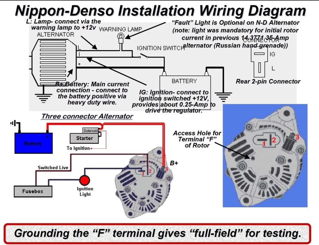
Marine Alternator Wiring Diagram Many alternators require ignition voltage to initiate charging. you must verify that all required connections are connected to the proper terminal and have the correct voltage in order for the alternator to operate properly. below you will find the most common alternator circuits used on marine applications. alternator circuits. Here is a summary of the steps involved in wiring a boat alternator: gather the necessary tools and materials. before you begin, make sure you have all the required tools and materials, including wire, connectors, crimping tool, electrical tape, and a wiring diagram for your specific alternator. disconnect the battery. The sae j1171 marine alternator wiring diagram includes a number of components that must be connected correctly in order for the system to work properly. this includes the alternator, battery, switches, fuses, and relays. in addition, the diagram also shows how to connect the alternator to the boat's power source, such as a generator or shore. The alternator is responsible for converting mechanical energy from the engine into electrical energy to charge the battery and power the boat’s electrical system. it is important to follow the correct wiring diagram to ensure the alternator is connected properly and functions effectively. step 1: disconnect the battery.

4 Pin Alternator Wiring Diagram The sae j1171 marine alternator wiring diagram includes a number of components that must be connected correctly in order for the system to work properly. this includes the alternator, battery, switches, fuses, and relays. in addition, the diagram also shows how to connect the alternator to the boat's power source, such as a generator or shore. The alternator is responsible for converting mechanical energy from the engine into electrical energy to charge the battery and power the boat’s electrical system. it is important to follow the correct wiring diagram to ensure the alternator is connected properly and functions effectively. step 1: disconnect the battery. Alternators. grounding most balmar marine alternators are case ground. it is essential that the alternator is properly grounded. we strongly recommend you ground your alternator to the preferred engine ground or system ground bus with a cable that’s the same size as your output cable. if your alternator is. The red wire in the ford harness supplies positive field current and it returns via the alternator b not the regulator b . on average, with a typical marine alternator at full field, we measure 0.1a to 0.3a on regulator b black. on the standard balmar harness this amounts to roughly a 0.03% voltage drop.

Alternator Wiring Diagram Pdf Alternators. grounding most balmar marine alternators are case ground. it is essential that the alternator is properly grounded. we strongly recommend you ground your alternator to the preferred engine ground or system ground bus with a cable that’s the same size as your output cable. if your alternator is. The red wire in the ford harness supplies positive field current and it returns via the alternator b not the regulator b . on average, with a typical marine alternator at full field, we measure 0.1a to 0.3a on regulator b black. on the standard balmar harness this amounts to roughly a 0.03% voltage drop.

Comments are closed.