Honeywell Smart Gas Valve Wiring Diagram Wiring Diagram

Honeywell Smart Gas Valve Wiring Diagram Wiring Diagram 1 troubleshooting. 2 sequence of operation. download this manual. line voltage polarity sense models. application. the sv9520h smartvalve™ system controls combines. gas flow control and electronic direct main burner ignition. sequencing functions into a single unit. the ignition. The sv9401 sv9402 sv9403, sv9501 sv9502 sv9503, and sv9601 sv9602 are mounted in the appliance vestibule on the gas manifold. make sure the mounting location protects the control from dripping water and excessive humidity. make sure the mounting location maximum and minimum ambient temperature are both within the specified acceptable range.

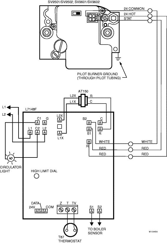
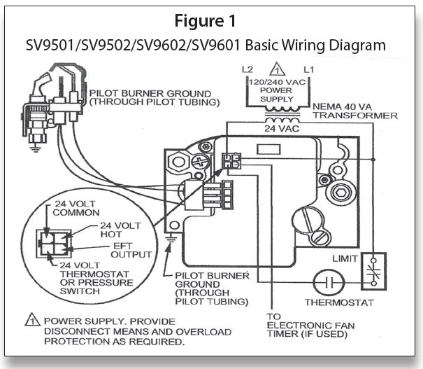
The Gas Sideâ Honeywell Smartvalvesâ Part 6 Indoor Comfort Marketing In this hvac training video, i show how this 120v & 24v honeywell smart valve (gas valve) works, how its wired, and how to troubleshoot. i built a display of. Honeywell tradeline sv9501 installation manual. system models. gas appliance manufacturers use these. heaters. these tradeline® controls provide. a single control. they are directly compatible with the. original controls on the appliance. sv9501, and sv9502 models noted in table 5. The sv9501 and sv9502 look slightly different from the sv9500. the sv9500 features an on off control knob, as shown in fig. 1. the sv9501, sv9502, sv9602, and sv9601 have an on off switch, as shown in fig. 2. the sv9501, sv9502, sv9601, and sv9602 have a connector located at the top of the valve instead of on the front. The wiring diagram of a honeywell smart valve provides a visual representation of how the device should be connected to the other components of the heating system. it shows the various terminals of the smart valve and how they should be connected to the power source, thermostat, gas supply, and other relevant components.

Honeywell Gas Valve Wiring Diagram The sv9501 and sv9502 look slightly different from the sv9500. the sv9500 features an on off control knob, as shown in fig. 1. the sv9501, sv9502, sv9602, and sv9601 have an on off switch, as shown in fig. 2. the sv9501, sv9502, sv9601, and sv9602 have a connector located at the top of the valve instead of on the front. The wiring diagram of a honeywell smart valve provides a visual representation of how the device should be connected to the other components of the heating system. it shows the various terminals of the smart valve and how they should be connected to the power source, thermostat, gas supply, and other relevant components. Your wiring will match one of the options below. if you do not see your wiring listed, we recommend using our on line compatibility checker. 1h 1c conventional gas oil electric forced air system (1 transformer): r wire power [r rc joined by jumper] y wire compressor contactor. c wire 24vac common. If you have a c wire, place it into the c terminal on your wall plate. c wire adapters are available here. let’s look at the g wire. this wire goes to the g terminal on your new thermostat. of the y, y1, and y2 wires, y or y1 go to the y terminal and y2 to the y2 terminal. the o b wire can have many configurations.

Honeywell Smart Gas Valve Wiring Diagram Wiring Diagram Your wiring will match one of the options below. if you do not see your wiring listed, we recommend using our on line compatibility checker. 1h 1c conventional gas oil electric forced air system (1 transformer): r wire power [r rc joined by jumper] y wire compressor contactor. c wire 24vac common. If you have a c wire, place it into the c terminal on your wall plate. c wire adapters are available here. let’s look at the g wire. this wire goes to the g terminal on your new thermostat. of the y, y1, and y2 wires, y or y1 go to the y terminal and y2 to the y2 terminal. the o b wire can have many configurations.

Honeywell Smart Gas Valve Wiring Diagram Wiring Diagram

Comments are closed.