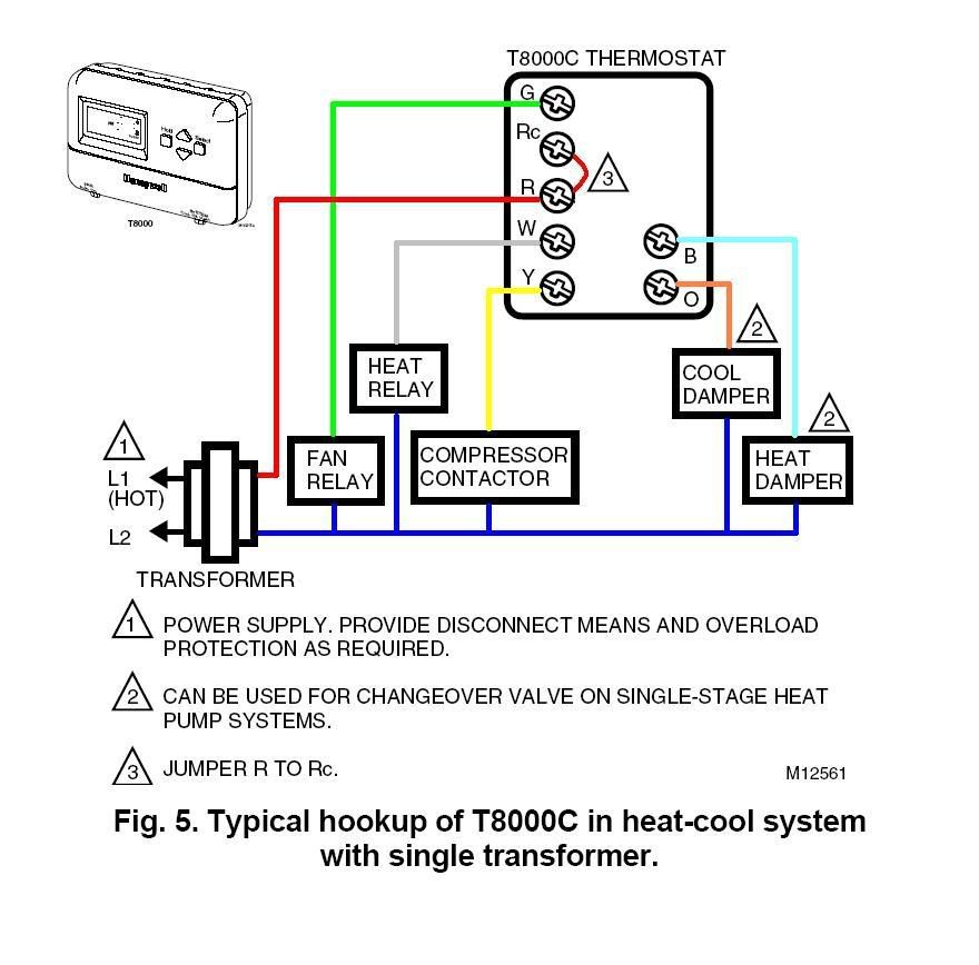
Honeywell Heating Cooling Thermostat Wiring Diagram

Honeywell Ct87n4450 Thermostat Wiring Diagram If you have a c wire, place it into the c terminal on your wall plate. c wire adapters are available here. let’s look at the g wire. this wire goes to the g terminal on your new thermostat. of the y, y1, and y2 wires, y or y1 go to the y terminal and y2 to the y2 terminal. the o b wire can have many configurations. The thermostat uses 1 wire to control each of your hvac system’s primary functions, such as heating, cooling, fan, etc. see the diagram below for what each wire controls on your system: y – compressor stage 1 (cooling) y2 – compressor stage 2 (cooling) g – fan c – common l a – a – input for heat pump fault.

Honeywell Thermostat Wiring 4 Wires Before beginning the installation be aware that that the t5 smart thermostat: is compatible with most heating, cooling, and heat pump systems; requires 24 vac power (“c” wire). c wire power adapter included to provide power if needed; does not work with electric baseboard heat (120v 240v) does not work with millivolt systems. One of the most common issues is incorrect wiring connections. ensure that the wires are correctly attached to the terminals on both the thermostat and the heating cooling system. refer to the wiring diagram in the thermostat’s manual to verify the correct connections. 2. loose or damaged wires: check for any loose or damaged wires. Wire the thermostat 1. use the wiring cross reference table below to match each old thermostat wire with its corresponding terminal on the ct87 wallplate or subbase. see fig. 8 through 13 wiring diagrams. *never attach wires to both the b and o terminals. 2. strip the wire insulation as needed to fit the wires underneath the ter minal screws. In the case of the honeywell th3210d1004 thermostat, the wiring diagram will typically include terminals such as r, c, w, y, g, and o b. these terminals correspond to the different wires that connect your thermostat to the heating and cooling system. for example, the r terminal is usually connected to the transformer and provides a power source.

Honeywell Thermostat Wiring Schematic Wire the thermostat 1. use the wiring cross reference table below to match each old thermostat wire with its corresponding terminal on the ct87 wallplate or subbase. see fig. 8 through 13 wiring diagrams. *never attach wires to both the b and o terminals. 2. strip the wire insulation as needed to fit the wires underneath the ter minal screws. In the case of the honeywell th3210d1004 thermostat, the wiring diagram will typically include terminals such as r, c, w, y, g, and o b. these terminals correspond to the different wires that connect your thermostat to the heating and cooling system. for example, the r terminal is usually connected to the transformer and provides a power source. There are also differences when it comes to the wiring in your home that, with the help of your thermostat, controls the heating and cooling system. if you check the honeywell thermostat ct31a1003 wiring diagram, for example, you'll see that it requires only two wires because it's a very basic thermostat designed only to control a heating system. Mount the new thermostat: position the new thermostat mounting plate on the wall and screw it in place. make sure it is level and secure. 5. connect the wires: take the wires from the wall and connect them to the corresponding terminals on the new thermostat. use a screwdriver to secure the wires in place. 6.

Comments are closed.