Honeywell Gas Valve Wiring Diagram

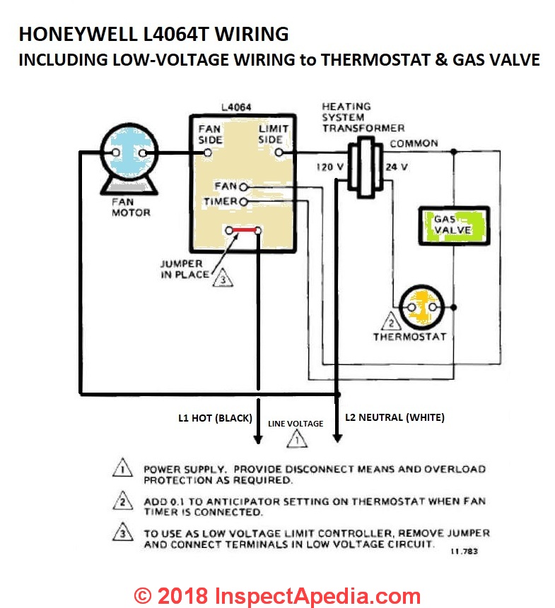
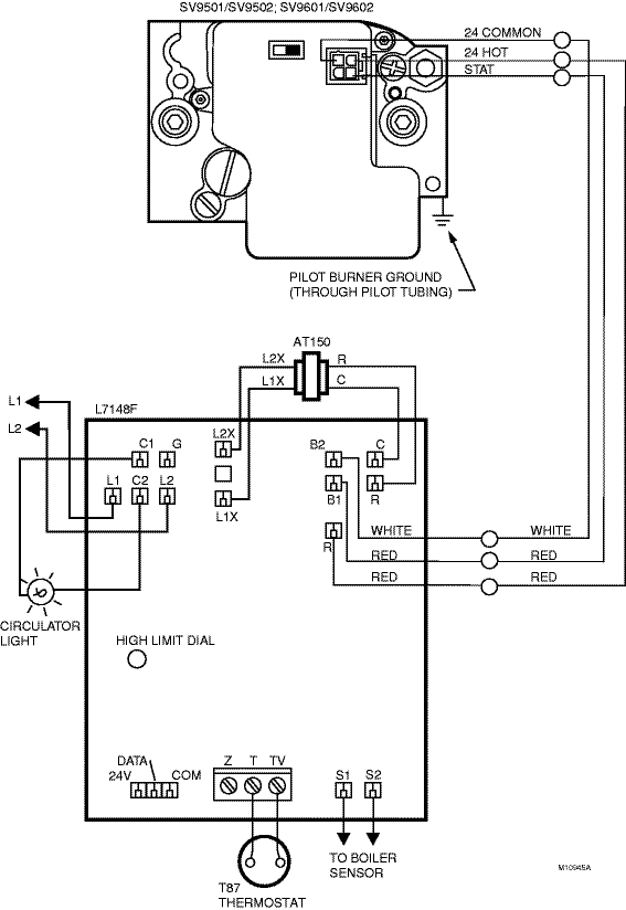
Honeywell Vr8200 Gas Valve Wiring Diagram 1 troubleshooting. 2 sequence of operation. download this manual. line voltage polarity sense models. application. the sv9520h smartvalve™ system controls combines. gas flow control and electronic direct main burner ignition. sequencing functions into a single unit. the ignition. The sv9501 wiring diagram is a crucial tool for understanding the electrical connections and components of the honeywell sv9501 gas valve. this diagram uses various symbols and codes to represent different elements, and understanding these symbols is essential for proper installation and troubleshooting. symbols:.

Honeywell Smart Gas Valve Wiring Diagram Wiring Diagram Regulator setting in replacement control differs from original. adjust to rated pressure as necessary for optimum performance. shipped by honeywell as lp gas only; may have been converted to natural gas. use natural to lp gas conversion kit (included) if necessary. follow instructions in conversion kit. page 16 sv9602p4824 as the replacement. The sv9401 sv9402 sv9403, sv9501 sv9502 sv9503, and sv9601 sv9602 are mounted in the appliance vestibule on the gas manifold. make sure the mounting location protects the control from dripping water and excessive humidity. make sure the mounting location maximum and minimum ambient temperature are both within the specified acceptable range. If the gas control knob does not operate by hand, the gas control should be replaced by a qualified service technician. force or attempted repair can result in fire or explosion. 69 1024 5. caution. equipment damage. can burn out heat anticipator in thermostat. never apply a jumper across or short the valve coil terminals. Application. the sv9541 and sv9641 smartvalvetm system controls combine gas flow control and electronic intermittent pilot sequencing functions into a single unit. the q3450 or q3480 pilot hardware supplies the low voltage igniter, flame sensor and pilot burner. these ignition system controls provide all gas ignition safety functions by.

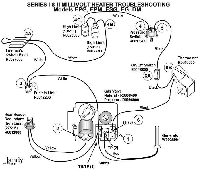
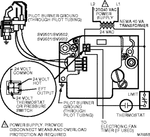
Honeywell Millivolt Gas Valve Wiring Diagram Sharp Wiring If the gas control knob does not operate by hand, the gas control should be replaced by a qualified service technician. force or attempted repair can result in fire or explosion. 69 1024 5. caution. equipment damage. can burn out heat anticipator in thermostat. never apply a jumper across or short the valve coil terminals. Application. the sv9541 and sv9641 smartvalvetm system controls combine gas flow control and electronic intermittent pilot sequencing functions into a single unit. the q3450 or q3480 pilot hardware supplies the low voltage igniter, flame sensor and pilot burner. these ignition system controls provide all gas ignition safety functions by. The sv9501 and sv9502 look slightly different from the sv9500. the sv9500 features an on off control knob, as shown in fig. 1. the sv9501, sv9502, sv9602, and sv9601 have an on off switch, as shown in fig. 2. the sv9501, sv9502, sv9601, and sv9602 have a connector located at the top of the valve instead of on the front. A comprehensive guide on understanding the wiring diagram for the honeywell vs820 gas valve. learn about the different components and their connections to ensure proper installation and troubleshooting. get expert insights and tips to optimize the performance of your gas valve and ensure safety.

Honeywell Gas Valve Wiring Diagram Wiring Diagram The sv9501 and sv9502 look slightly different from the sv9500. the sv9500 features an on off control knob, as shown in fig. 1. the sv9501, sv9502, sv9602, and sv9601 have an on off switch, as shown in fig. 2. the sv9501, sv9502, sv9601, and sv9602 have a connector located at the top of the valve instead of on the front. A comprehensive guide on understanding the wiring diagram for the honeywell vs820 gas valve. learn about the different components and their connections to ensure proper installation and troubleshooting. get expert insights and tips to optimize the performance of your gas valve and ensure safety.

Honeywell Gas Valve Wiring Diagram Wiring Diagram

Honeywell Gas Valve Wiring Diagram Schema Digital

Comments are closed.