Heat Cool Thermostat Wiring Diagram

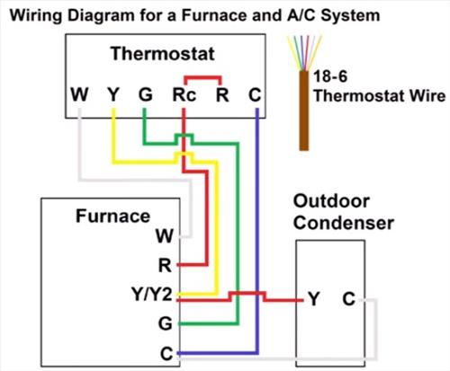
Thermostat Wiring Explained These control the power, heat and fan. standard thermostats use 4 or 5 wires: r, w, g, y, and sometimes c. these control the power, heat, fan, and cooling. more advanced thermostats use 6 8 wires. the extra wires control additional hvac system features and settings, signaling a two stage cooling or heat pump system. 7). attach the orange wire to the o terminal for reversing valve for cooling. 8 wire thermostat wiring. here is the most common use of 8 wires. what uses 8 wire thermostat wiring? these are almost always heat pump hvac systems aux heat. how to wire an 8 wire thermostat: 1). attach the red wire to the r terminal for 24v power. 2).

Heat Cool Thermostat Wiring Unscrew the two wires from the terminals. remove the motherboard of the old 2 wire thermostat and put the new 2 wire thermostat in its place. reconnect the red and white wire, tighten down the set screw, and put the control panel back on. test the 2 wire thermostat wiring by turning the furnace on. The y wire is yellow and connects to your air conditioning compressor. the g wire is green and connects to the fan. rc and rh: the red wire(s) are the power source for your thermostat. if your thermostat is dedicated to air conditioning only, it will have a red rc wire. for heating and cooling systems, it will have a red rc and a red rh wire. Learn how to wire your thermostat with this step by step guide from honeywell home. see the diagram and instructions for different wiring configurations and system types. Y or y1: yellow thermostat wire. in traditional cooling systems, the yellow wire controls the cooling function. in a heat pump, it controls the compressor, which can both heat and cool your home. the yellow wire is connected to the y or y1 terminal on your thermostat. in a multi stage cooling system, this serves as the first stage.

Heating And Cooling Thermostat Wiring Diagram Collection Learn how to wire your thermostat with this step by step guide from honeywell home. see the diagram and instructions for different wiring configurations and system types. Y or y1: yellow thermostat wire. in traditional cooling systems, the yellow wire controls the cooling function. in a heat pump, it controls the compressor, which can both heat and cool your home. the yellow wire is connected to the y or y1 terminal on your thermostat. in a multi stage cooling system, this serves as the first stage. G – green: this wire controls the blower motor in the furnace. y2 – light blue: this wire is necessary if you have a two stage ac compressor. if the ac is single stage, this terminal will be empty. w2 – light brown: this wire functions like the light blue wire but for furnaces with low and high stages of heating. Disconnect the wires. once you’ve located all the wires, taken a photo, and labeled where everything goes, it’s time to disconnect the wires and the mounting screws. make sure to tape the wires down so they don’t fall inside the wall. remove any anchor screws and the backplate of the existing thermostat.

Cync Thermostat Wiring Configuration And Installation Guide G – green: this wire controls the blower motor in the furnace. y2 – light blue: this wire is necessary if you have a two stage ac compressor. if the ac is single stage, this terminal will be empty. w2 – light brown: this wire functions like the light blue wire but for furnaces with low and high stages of heating. Disconnect the wires. once you’ve located all the wires, taken a photo, and labeled where everything goes, it’s time to disconnect the wires and the mounting screws. make sure to tape the wires down so they don’t fall inside the wall. remove any anchor screws and the backplate of the existing thermostat.

Cync Thermostat Wiring Configuration And Installation Guide

Home Heating Thermostat Wiring Diagram Wiring Diagram And Schematics

Comments are closed.