Glow Plug Relay Wiring Diagram Schema Digital

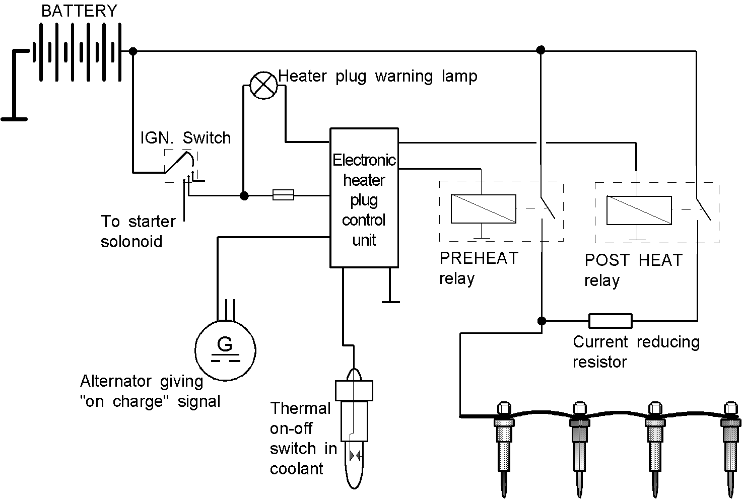
Wiring Diagram For Glow Plug Relay Wiring Digital And Schematic The 4 pin glow plug relay provides a robust connection between the glow plugs and the spark plugs, which is essential for proper engine performance. it is important for the spark plugs and glow plugs to be connected correctly, as a miswired relay can cause severe engine damage. Glow plug wiring diagram. wiring up manual glow plug switch ford truck enthusiasts forums. yet another glow plug thread 81 hj47 ih8mud forum. 1995 6 5 glow plug relay issues sel ers. vw sel glow plugs. mercedes sel glow plug repair. glow plug relay wiring 93 f250 non turbo sel ers. gp relay wiring causing issues the sel stop. techdoc. glow plug.
Glow Plug Relay Wiring Diagram Schema Digital Next verify relay is changing state and that voltage is being supplied to the glow plugs. timer should time out and shut relay off. remove wire to glow plug and check resistance of each glow plug. they should be similar from one plug to the next. not sure what amperage the glow plugs draw so i would be careful trying to check amp draw with. 85 gp controller wiring sel place. techniek ombouw 24v 12v chaosboyz 4x4. pureflow selrx glow plugs for 1984 1986 military cucv detroit 6 2l com. glow plug inhibit switch steelsolrs. 4agze silicone vacuum hoses photo gallery by aw11mr2 at pbase com. cucv glow plug system diagnosis manualzz. The switch is closed, sending current out pin 87 to the glow plugs (hm9) and the light micro relay (hm99), by a voltage drop across pins 86 and 85 (left side of diagram). turning the switch to "ignition" or "start" puts 12v at pin 86 (upper right), so the glow plugs are triggered by sending ground to pin 85 (lower left). I think i found the diagram on wis. pin 8 on relay to glow plug 1 bkbu. pin 7 on relay to glow plug 2 bkvt. pin 6 on relay to glow plug 3 bkrd. pin 5 on relay to glow plug 4 bkye. i'm praying it's the relay dead, even though part more expensive, changing glow plugs is a days work. i can test resistance but with out direct access to glow plugs.

Glow Plug Relay Wiring Diagram Schema Digital The switch is closed, sending current out pin 87 to the glow plugs (hm9) and the light micro relay (hm99), by a voltage drop across pins 86 and 85 (left side of diagram). turning the switch to "ignition" or "start" puts 12v at pin 86 (upper right), so the glow plugs are triggered by sending ground to pin 85 (lower left). I think i found the diagram on wis. pin 8 on relay to glow plug 1 bkbu. pin 7 on relay to glow plug 2 bkvt. pin 6 on relay to glow plug 3 bkrd. pin 5 on relay to glow plug 4 bkye. i'm praying it's the relay dead, even though part more expensive, changing glow plugs is a days work. i can test resistance but with out direct access to glow plugs. The diagrams typically show the wiring layout of the glow plug relay system, including the glow plug relay, the wiring harness, and the fuse box. the diagrams also usually show the colors of the wires and the location of the connectors. additionally, the diagrams will often include labels indicating the purpose of each wire and connector. Build the glow plug control module unit on any general purpose pcb and mount it in a suitable case box. connect the glow plug wire to the relay contact. the 12v battery source that already available with the vehicle can be used to power the circuit. connect the piezobuzzer and led1 and led2 through an external connection and place it at a.
Bosch Glow Plug Relay Wiring Diagram The diagrams typically show the wiring layout of the glow plug relay system, including the glow plug relay, the wiring harness, and the fuse box. the diagrams also usually show the colors of the wires and the location of the connectors. additionally, the diagrams will often include labels indicating the purpose of each wire and connector. Build the glow plug control module unit on any general purpose pcb and mount it in a suitable case box. connect the glow plug wire to the relay contact. the 12v battery source that already available with the vehicle can be used to power the circuit. connect the piezobuzzer and led1 and led2 through an external connection and place it at a.

Wiring Diagram For Glow Plug Relay 73

Comments are closed.