Freeform Optics Produces A New Wave Of Integration Jun 2020

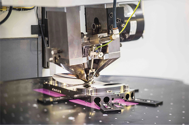
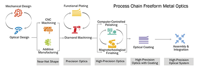
Freeform Optics Produces A New Wave Of Integration Jun 2020 For the device 2 shown in figure 3, they are: 1. a freeform tool stroke of ≤6 mm. 2. azimuthal gradients of ≤10° (angle of clearance ≤20°). 3. azimuthal accelerations of ≤5 g (frequency responses allow 0:2 to 7:5 g). a new two dimensional algorithm has been developed by fraunhofer iof for this procedure. Freeform optics produces a new wave of integration a cohesive workflow and precision 3d printing have allowed for adapting multiple elements in manufacturing. matthias beier and johannes hartung, fraunhofer institute for applied optics and precision engineering iof.

Freeform Optics Produces A New Wave Of Integration Jun 2020 Freeform optical systems, aberrations, and their mathematical description. there are various possibilities to classify aberrations in freeform optical systems 53,54.for the design method presented. In the last 10 years, freeform optics has enabled compact and high performance imaging systems. this article begins with a brief history of freeform optics, focusing on imaging systems, including marketplace emergence. the development of this technology is motivated by the clear opportunity to enable science across a wide range of applications, spanning from extreme ultraviolet lithography to. Of freeform elements in the next gen eration of high end imaging systems. a more detailed mathematical descrip tion can be found in a recently published article [2]. mathematical formulation. there are various possibilities to clas sify aberrations in freeform optical sys tems according to the overall system symmetry present: (1) systems with. A 5 × 5 tunable microlens array (d = 540 μm; fig. 5a) is located 5 mm before the image plane to maximize the refocusing range and minimize crosstalk between microlenses. a ×1.5 telescope.

Freeform Optics Produces A New Wave Of Integration Jun 2020 Of freeform elements in the next gen eration of high end imaging systems. a more detailed mathematical descrip tion can be found in a recently published article [2]. mathematical formulation. there are various possibilities to clas sify aberrations in freeform optical sys tems according to the overall system symmetry present: (1) systems with. A 5 × 5 tunable microlens array (d = 540 μm; fig. 5a) is located 5 mm before the image plane to maximize the refocusing range and minimize crosstalk between microlenses. a ×1.5 telescope. An optical system is an assembly of optical components that operate together to produce a desired function 1.optical design involves determining all the data required to describe an optical system. Nonimaging and illumination optics have leveraged freeform surfaces since at least the 1990s [1]. integration of freeform optics and surfaces into imaging systems remains as a major challenge. however, the new degrees of freedom introduced by freeform optics designs are the driver to overcoming these challenges.

Comments are closed.