Drilled Shafts Guide Casings Liners
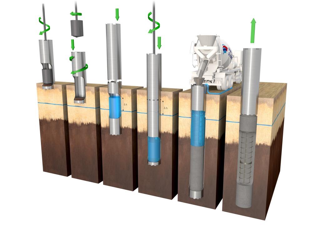
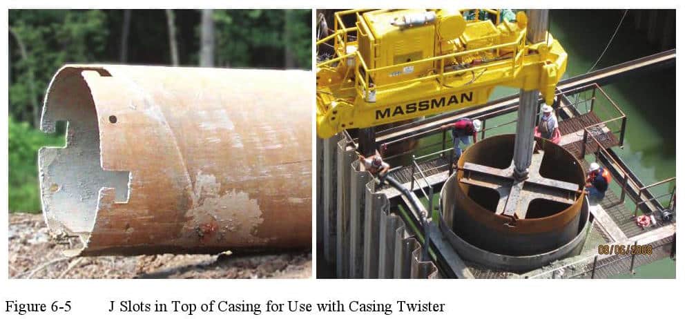
Drilled Shafts Guide Casings Liners While liners are not used as frequently as casings, liners are critical in certain construction projects. this article will discuss the two main types of casings and liners that may be used in drilled shaft construction: temporary and permanent. the type of casing or liner that is used will depend on a number of factors, as described in depth. Casings and liners are used in conjunction with rotary drilling or other techniques described in chapters 4 and 5 for constructing drilled shafts. casings are tubes that are relatively strong, usually made of steel, and joined, if necessary, by welding or, in some cases, bolting. casings may also have special joints that allow torque and axial.
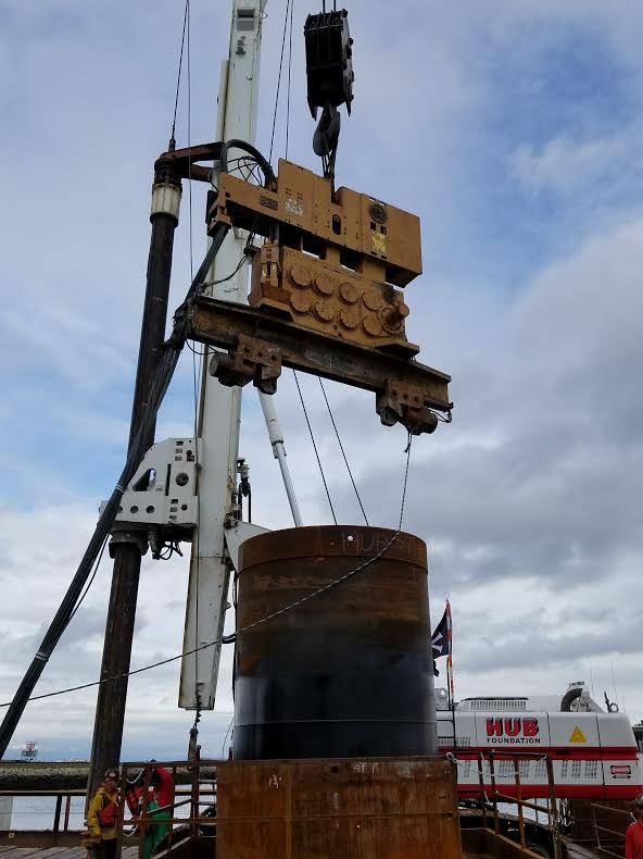
Drilled Shafts Guide Casings Liners Casings and liners play an important role in the construction of drilled shafts, and special attention must be given to their selection and use. casings are tubes that are relatively strong, usually made of steel, and joined, if necessary, by welding. liners, on the other hand, are light in weight and become a permanent part of the foundation. 20 percent increase in resistance factors allowed for groups of five or more drilled shafts. example: j = 1.2 x 0.55 = 0.66. for static load testing, max resistance factor of 0.70 allowed. for groups of 5 or more shafts, incentive to conduct static load testing is thus greatly diminished. reconsider the 20 percent increase for groups of 5 or. Excavation prior to pouring concrete. drilled shafts have also been called bored piles, cast in situ piles, drilled piers, and caissons. the soil is excavated either by use of rotary drilling equipment or by use of the percussion method. both procedures typically use a surface casing or guide to initiate drilling. excavation is. Drilled shafts for structural support can be installed by the dry (open hole), stabilizing polymer slurry, or steel cased methods. the permanent casing is typically only specified in corrosive environments, voided (open cavity) conditions, or for shafts drilled through the water. the temporary casing may also be required for open hole shaft.
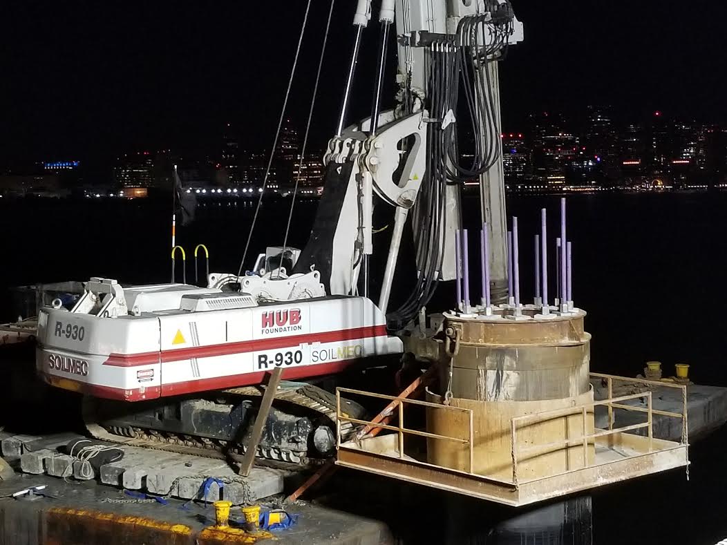
Drilled Shafts Guide Casings Liners Excavation prior to pouring concrete. drilled shafts have also been called bored piles, cast in situ piles, drilled piers, and caissons. the soil is excavated either by use of rotary drilling equipment or by use of the percussion method. both procedures typically use a surface casing or guide to initiate drilling. excavation is. Drilled shafts for structural support can be installed by the dry (open hole), stabilizing polymer slurry, or steel cased methods. the permanent casing is typically only specified in corrosive environments, voided (open cavity) conditions, or for shafts drilled through the water. the temporary casing may also be required for open hole shaft. From drilled shafts: construction procedures and lrfd design methods by fhwa. 1.1 introduction – purpose and organization of manual. this publication is intended to provide a resource for engineers responsible for the selection and design of drilled shaft foundations for transportation structures and as a text for use with the three day short course on the subject presented by the national. Belled shafts are normally conical in shape. the cylindrical shaft is drilled first and the auger is removed, the belling tool is then attached to cut the soil to form a belled shape at the bottom of the cylindrical shaft. see figure no. 1 below. the rebar cage will extend through the center of the shaft and the bell.
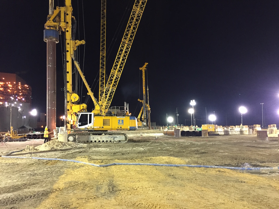
Drilled Shafts Guide Casings Liners From drilled shafts: construction procedures and lrfd design methods by fhwa. 1.1 introduction – purpose and organization of manual. this publication is intended to provide a resource for engineers responsible for the selection and design of drilled shaft foundations for transportation structures and as a text for use with the three day short course on the subject presented by the national. Belled shafts are normally conical in shape. the cylindrical shaft is drilled first and the auger is removed, the belling tool is then attached to cut the soil to form a belled shape at the bottom of the cylindrical shaft. see figure no. 1 below. the rebar cage will extend through the center of the shaft and the bell.
Chapter 6 Casings And Liners Pile Buck Magazine

Comments are closed.