Draw A Diagram Of 2 Reference Frame

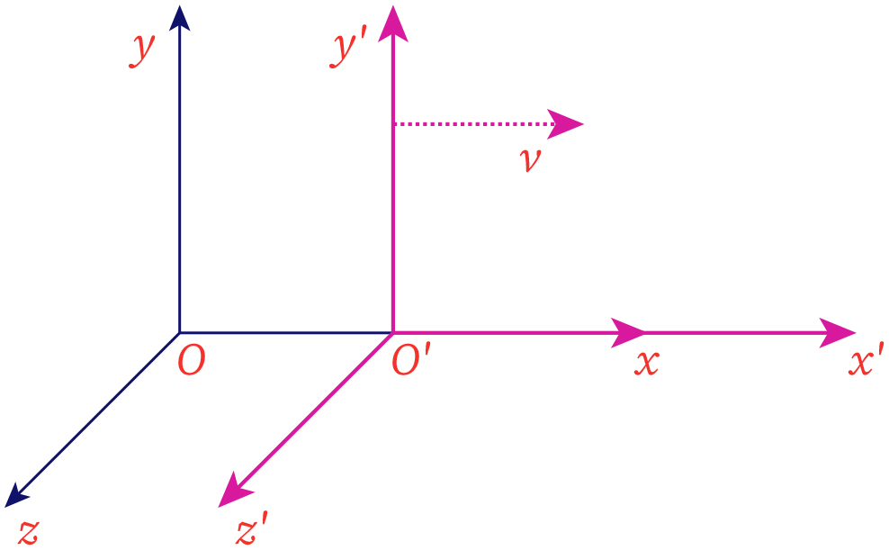
Frame Of Reference Bartleby The vector equation is →vpg = →vpa →vag, where p = plane, a = air, and g = ground. from the geometry in figure 4.6.6, we can solve easily for the magnitude of the velocity of the plane with respect to the ground and the angle of the plane’s heading, θ. figure 4.6.6: vector diagram for equation 4.6.2 showing the vectors →vpa, →vag. 11.3 law of addition of velocities: newtonian mechanics. suppose the object in figure 11.1 is moving; then observers in different reference frames will measure different velocities. denote the velocity of the object in frame s by. v . = dr dt , and the velocity of the object in frame s′ by v′ = dr′ dt′ .

Top View Of The Two Reference Frames Download Scientific Diagram So it is just a simple frame change: let the earth frame be frame e and the frame moving with object 1 be frame 1, then the velocity we want is v12 (“velocity of object 2 in frame 1”). if we make the change a → 1, b → e, and p → 2 in equation (1.3.7), we get. v12 = ve2 − ve1. in other words, the velocity of 2 relative to 1 is just. An inertial reference frame is a frame of reference in which newton’s first law of motion holds true—that is, an object either remains at rest or continues to move at a constant velocity, unless acted upon by a net external force. essentially, in an inertial frame, there are no unexplained forces acting on the bodies within the frame. Figure 1: path of the ball as seen by an observer on the train and an observer at the station. the different observations occur because the two observers are in different frames of reference. a frame of reference is a set of coordinates that can be used to determine positions and velocities of objects in that frame; different frames of. Unless explicitly mentioned, for the rest of this textbook we only deal with dynamics in inertial reference frames (irfs). this page titled 6.12: relative motion and inertial reference frames is shared under a cc by 4.0 license and was authored, remixed, and or curated by peter g. steeneken via source content that was edited to the style and.
2 Reference Frames Used In This Study Download Scientific Diagram Figure 1: path of the ball as seen by an observer on the train and an observer at the station. the different observations occur because the two observers are in different frames of reference. a frame of reference is a set of coordinates that can be used to determine positions and velocities of objects in that frame; different frames of. Unless explicitly mentioned, for the rest of this textbook we only deal with dynamics in inertial reference frames (irfs). this page titled 6.12: relative motion and inertial reference frames is shared under a cc by 4.0 license and was authored, remixed, and or curated by peter g. steeneken via source content that was edited to the style and. A spatial representation of its links in the 2d or 3d world in which it operates, e.g., matrices describing the frame of each link relative to some world coordinate system. the list of joint coordinates are known as the configuration of the robot. the 2d or 3d world in which the robot lives is known as its workspace. Interactive minkowski diagram spacetime diagram. the diagram in a pop up window tutorial examples and excercises answers sources. this interactive minkowski diagram is based on the conventional setting of c = 1. units along the axis may be interpreted as: t unit = second, then d unit = lightsecond, or alternatively, d unit = m, t unit.

Two Reference Frames Download Scientific Diagram A spatial representation of its links in the 2d or 3d world in which it operates, e.g., matrices describing the frame of each link relative to some world coordinate system. the list of joint coordinates are known as the configuration of the robot. the 2d or 3d world in which the robot lives is known as its workspace. Interactive minkowski diagram spacetime diagram. the diagram in a pop up window tutorial examples and excercises answers sources. this interactive minkowski diagram is based on the conventional setting of c = 1. units along the axis may be interpreted as: t unit = second, then d unit = lightsecond, or alternatively, d unit = m, t unit.

Schematic Diagram Of The Two Phase Rotating Reference Frame Download

Two Reference Frames Download Scientific Diagram

Comments are closed.