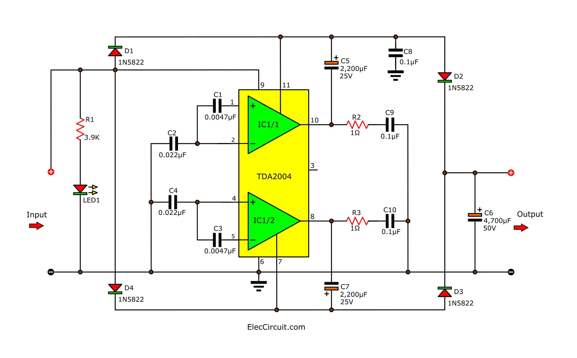
Dc Dc Step Up Converter Schematic

Dc Step Up Converter Schematic Download Scientific Diagram The basic components of the switching circuit can be rearranged to form a step down (buck) converter, a step up (boost) converter, or an inverter (flyback). these designs are shown in figures 1, 2, 3, and 4 respectively, where figures 3 and 4 are the same except for the transformer and the diode polarity. A boost converter (step up converter) is a dc to dc power converter that steps up voltage (while stepping down current) from its input (supply) to its output (load). it is a class of switched mode power supply (smps) containing at least two semiconductors (a diode and a transistor) and at least one energy storage element: a capacitor, inductor.

12 To 24 Volt Dc Converter Circuits Electronic Projects Circuits A boost converter or step up converter is a dc to dc converter that increases voltage, while decreasing current, from its input to its output . it is a class of switched mode power supply (smps) containing at least two semiconductors, a diode and a transistor , and at least one energy storage element: a capacitor , inductor , or the two in. The boost converter is a dc to dc converter designed to perform the step up conversion of applied dc input. in the boost converter, the supplied fixed dc input is boosted (or increased) to adjustable dc output voltage i.e. output voltage of the boost converter is always greater than the input voltage. so, a boost converter is also called a step. A step up converter, also called a boost, is a dc dc power converter that increases the input voltage and provides a higher output voltage. the switching circuit consists of an electronic switch (a bjt, mosfet or other) that alternately switches on and off at a very high frequency (see general circuit diagram in figure 1). Introduction and principle of operation. boost converters are a type of dc dc switching converter that efficiently increase (step up) the input voltage to a higher output voltage. by storing energy in an inductor during the switch on phase and releasing it to the load during the switch off phase, this voltage conversion is made possible.

Tl494 Dc To Dc Boost Step Up Converter Smps 12v To 100volts Youtube A step up converter, also called a boost, is a dc dc power converter that increases the input voltage and provides a higher output voltage. the switching circuit consists of an electronic switch (a bjt, mosfet or other) that alternately switches on and off at a very high frequency (see general circuit diagram in figure 1). Introduction and principle of operation. boost converters are a type of dc dc switching converter that efficiently increase (step up) the input voltage to a higher output voltage. by storing energy in an inductor during the switch on phase and releasing it to the load during the switch off phase, this voltage conversion is made possible. High level circuit operating principle. a boost converter or step up converter aids in stepping up a dc voltage from the input to the output. the conduction state of the switch dictates the operation of the circuit. during the on state, the current flowing through the inductor increases linearly. the diode is not conducting. this is shown in. Step 2: figure 1 schematic diagram of the uc3843 dc to dc boost converter. c1 and c2 have been used to reduce the input noises. l1, d1, and q1 build a boost conversion network. l1 is an 8a to 10a 100uh inductor. d1 is the mbr20100ct [2] schottky diode (two parallel diodes in one package).

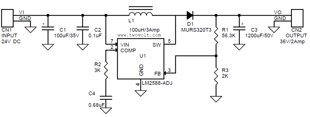
24v To 36v 2a Dc Dc Step Up Converter Using Lm2588 Electronics Lab High level circuit operating principle. a boost converter or step up converter aids in stepping up a dc voltage from the input to the output. the conduction state of the switch dictates the operation of the circuit. during the on state, the current flowing through the inductor increases linearly. the diode is not conducting. this is shown in. Step 2: figure 1 schematic diagram of the uc3843 dc to dc boost converter. c1 and c2 have been used to reduce the input noises. l1, d1, and q1 build a boost conversion network. l1 is an 8a to 10a 100uh inductor. d1 is the mbr20100ct [2] schottky diode (two parallel diodes in one package).

Comments are closed.