Circuit Symbols Diagrams The Learning Circuit

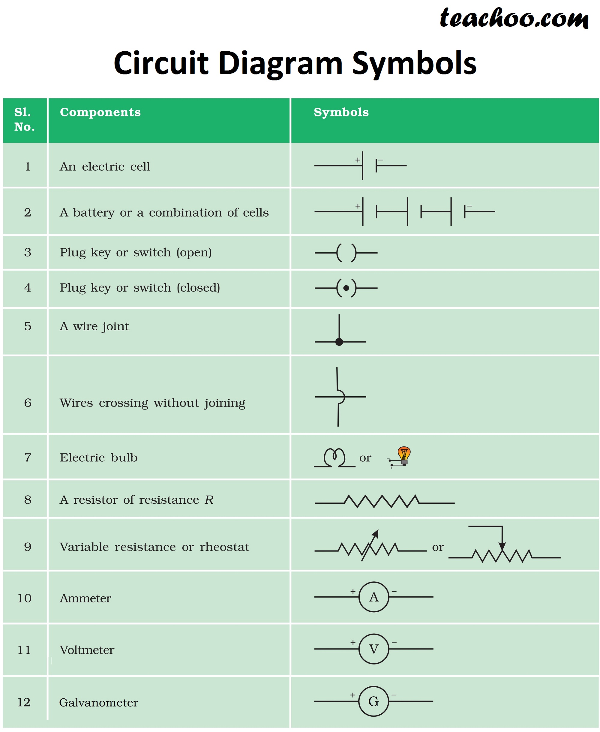
Electric Circuit Diagram Symbol Open And Closed Circuit Teachoo In electronics we use maps called circuit diagrams as a graphical representation of the connections and components in a circuit. follow along with karen as s. The learning circuit 60: how flip flops work. the learning circuit 59: using the access:bit with the micro:bit. the learning circuit 58: micro:bit add on zip halo led ring. the learning circuit 57: micro:bit diy compass. the learning circuit 56: micro:bit touch inputs.

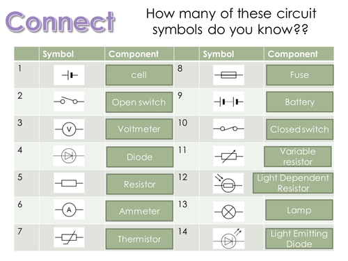
Circuit Symbols And Diagrams Lesson Teaching Resources An electrical schematic is a diagram that shows how all of the wires and components in an electronic circuit are connected. they’re like a map for building or troubleshooting circuits, and can tell you almost everything you need to know to understand how a circuit works. the ability to read electrical schematics is a really useful skill to have. Schematic symbols (part 1) are you ready for a barrage of circuit components? here are some of the standardized, basic schematic symbols for various components. resistors. the most fundamental of circuit components and symbols! resistors on a schematic are usually represented by a few zig zag lines, with two terminals extending outward. An electrical schematic is a graphical representation of an electrical circuit. it shows the connections and components of the circuit in a clear and concise manner. understanding the key components of an electrical schematic is essential for anyone working with electrical systems. 1. symbols: one of the most important elements of an electrical. Electrical circuit schematic symbols are graphical representations of different electrical components and devices used in circuit diagrams. these symbols help engineers, electricians, and technicians understand the various elements and their connections in a circuit without the need for detailed explanations. the use of standardized symbols in.

Circuit Symbols And Their Functions An electrical schematic is a graphical representation of an electrical circuit. it shows the connections and components of the circuit in a clear and concise manner. understanding the key components of an electrical schematic is essential for anyone working with electrical systems. 1. symbols: one of the most important elements of an electrical. Electrical circuit schematic symbols are graphical representations of different electrical components and devices used in circuit diagrams. these symbols help engineers, electricians, and technicians understand the various elements and their connections in a circuit without the need for detailed explanations. the use of standardized symbols in. Electrical & electronic symbols and images are used by engineers in circuit diagrams and schematics to show how a circuits components are connected together. circuit layouts and schematic diagrams are a simple and effective way of showing pictorially the electrical connections, components and operation of a particular electrical circuit or system. Electrical symbols & electronic circuit symbols of schematic diagram resistor, capacitor, inductor, relay, switch, wire, ground, diode, led, transistor, power.

Common Circuit Diagram Symbols Electrical & electronic symbols and images are used by engineers in circuit diagrams and schematics to show how a circuits components are connected together. circuit layouts and schematic diagrams are a simple and effective way of showing pictorially the electrical connections, components and operation of a particular electrical circuit or system. Electrical symbols & electronic circuit symbols of schematic diagram resistor, capacitor, inductor, relay, switch, wire, ground, diode, led, transistor, power.

Learn About Electricity Science For Kids Science Electricity

How To Read A Schematic Sparkfun Learn

Comments are closed.