Centrifugal Compressor Velocity Triangles And Slip In Compressor An

Centrifugal Compressor Velocity Triangles And Slip In Compressor An This video explains about velocity triangle analysis and work done by an impeller. Compressor example • axial air compressor stage with design point created for: 1. 8,000. rpm rotor with 0.30 m mean design radius 2. 100. m s axial velocity (constant through stage), 36.4 m s inlet tangential velocity 3. 50. rotor blade trailing edge angle (wrt to axis and opposite to rotation), and 20. stator blade’s trailing edge angle.

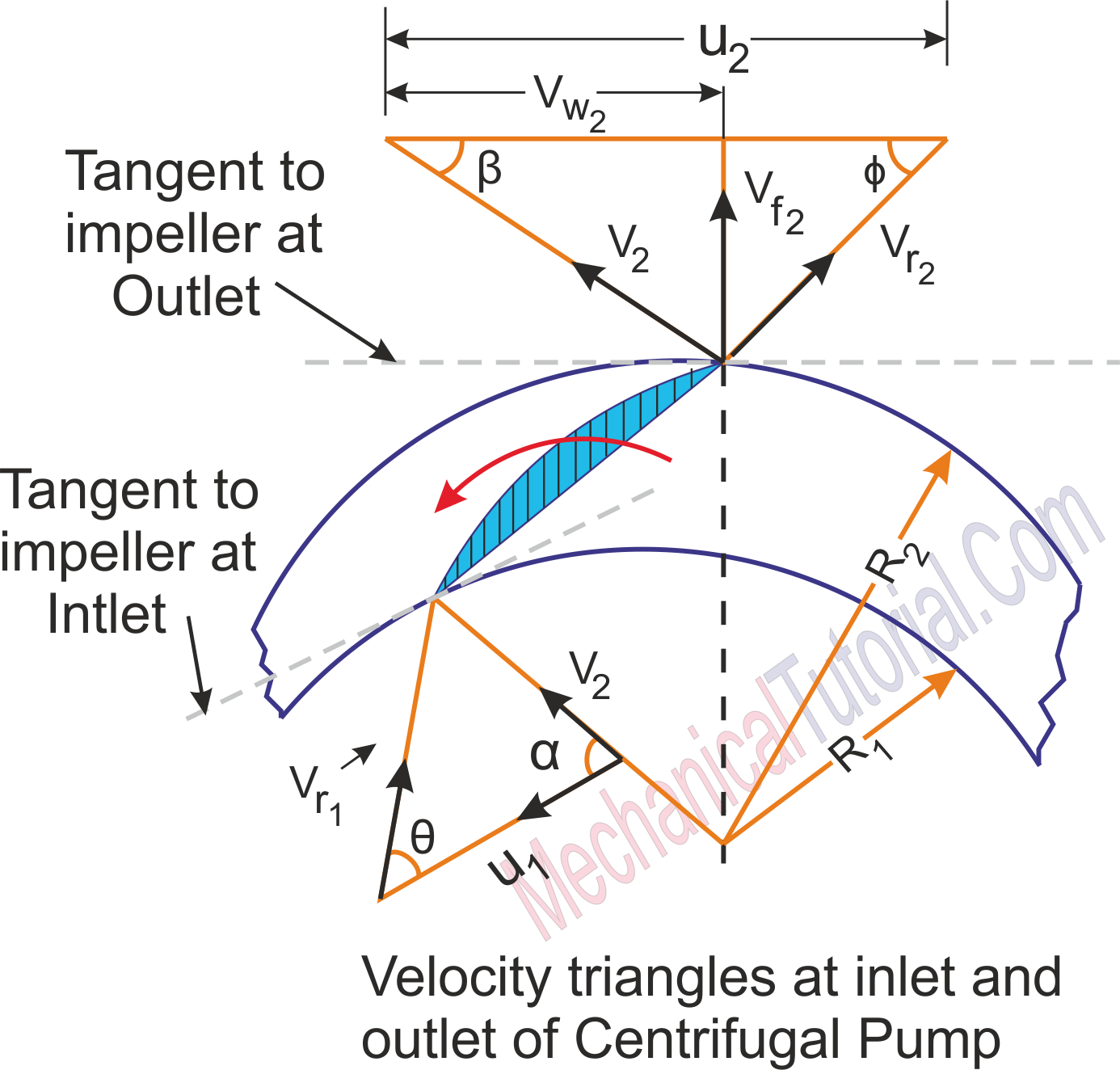
Velocity Diagram Of Centrifugal Compressor Youtube Subjects: velocity triangles; compressor performance maps . in the last lecture we discussed the basic mechanisms of energy exchange in compressors and drew some simple velocity triangles to show how we go from the stationary coordinate system to one in the moving blades. in more detail, the velocity triangle is: v. 1 = w. 1. tanβ. 1 . v. 2. Slip factor. in turbomachinery, the slip factor is a measure of the fluid slip in the impeller of a compressor or a turbine, mostly a centrifugal machine. fluid slip is the deviation in the angle at which the fluid leaves the impeller from the impeller's blade vane angle. being quite small in axial impellers (inlet and outlet flow in the same. Velocity triangle diagram for centrifugal compressor – when α1= 90 degree, β2= 90 degree (ii) if the air enters the impeller eye in an axial direction α1= 90 degree but air will not leaving the impeller in radial direction β2 < 90 degrees, vr2 ≠ vf2, and vw2 <vu2. velocity triangle diagram for centrifugal compressor. Preliminary design of centrifugal compressors. abstract with reference to a centrifugal compressor stage, a procedure for the calculation of kinematic parameters (sect. 6.1), thermodynamic parameters (sect. 6.2), geometric parameters (sect. 6.3) and stage losses (sect. 6.4) is provided. then, sect. 6.5 discusses the input parameters of this.

Velocity Triangles Diagram For Impeller Of Centrifugal Pump Fluid Velocity triangle diagram for centrifugal compressor – when α1= 90 degree, β2= 90 degree (ii) if the air enters the impeller eye in an axial direction α1= 90 degree but air will not leaving the impeller in radial direction β2 < 90 degrees, vr2 ≠ vf2, and vw2 <vu2. velocity triangle diagram for centrifugal compressor. Preliminary design of centrifugal compressors. abstract with reference to a centrifugal compressor stage, a procedure for the calculation of kinematic parameters (sect. 6.1), thermodynamic parameters (sect. 6.2), geometric parameters (sect. 6.3) and stage losses (sect. 6.4) is provided. then, sect. 6.5 discusses the input parameters of this. The slip factor plays a crucial role in the performance of a centrifugal compressor, affecting the pressure rise. solving problems related to centrifugal compressors requires a good understanding of velocity triangles and the physics behind them. Article shared by: in this article we will discus about: 1. construction and principle of operation of centrifugal compressor 2. velocity diagrams of a centrifugal compressor 3. work requirement (euler’s work) 4. slip factor 5. pressure ratio of compression 6. influence of impeller blade geometry 7. influence of compressor geometry on the.
Velocity Triangles Input Output In A Centrifugal Compressor The slip factor plays a crucial role in the performance of a centrifugal compressor, affecting the pressure rise. solving problems related to centrifugal compressors requires a good understanding of velocity triangles and the physics behind them. Article shared by: in this article we will discus about: 1. construction and principle of operation of centrifugal compressor 2. velocity diagrams of a centrifugal compressor 3. work requirement (euler’s work) 4. slip factor 5. pressure ratio of compression 6. influence of impeller blade geometry 7. influence of compressor geometry on the.

Centrifugal Pump Inlet And Outlet Velocity Triangles At Claudia Hawkins

Comments are closed.