Car Electric Fan Wire Relay Diagram

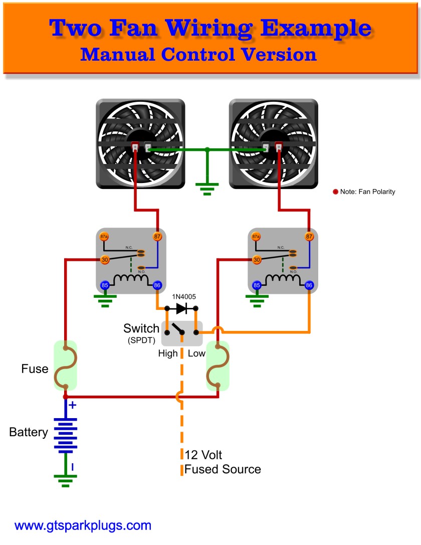
Automotive Electric Fan Relay Wiring Diagram This video shows how to easily wire an electric radiator fan circuit into any car. this fan wiring diagram includes a fan relay, a temperature switch, and a. With dual cooling fans, there are two methods for wiring up the relay kit. this is based on the draw from the fans, if the fans are larger and draw more than 15 amps each, it's recommended to install a second relay kit as shown below. for smaller fans, both fans can be connected to a single relay as shown above, and the proper fuse should be.

Car Electric Fan Wiring With Relay Optionally, a single high current relay could be used to control both fans. the supplied diagram below using dual relays with a single temp sensor is both the most reliable and easiest method we've found for wiring dual fans. it uses our 40 amp electric relay kit and electric fan sensor. the relay isolates the high amp load of the fan circuit. The wiring diagram of an automotive electric fan relay typically consists of four main components. firstly, there is the input power source, which is usually connected to the battery or ignition switch. secondly, there is the ground connection, which completes the circuit and allows the current to flow. Once the location is determined, the next step is to mount the relay securely using appropriate fasteners. next, you will need to connect the necessary wires to the relay. the wiring diagram will guide you in determining which wires to connect. typically, there will be power wires, ground wires, and wires connecting the fan to the relay. This will provide protection in case of electrical faults. 5. connect the fan: use the wire cutter stripper to cut another length of wire that will connect the relay to the fan. strip the ends of the wire and connect one end to the relay pin designated for the fan and the other end to the fan itself. 6.

Car Electric Fan Wiring With Relay Once the location is determined, the next step is to mount the relay securely using appropriate fasteners. next, you will need to connect the necessary wires to the relay. the wiring diagram will guide you in determining which wires to connect. typically, there will be power wires, ground wires, and wires connecting the fan to the relay. This will provide protection in case of electrical faults. 5. connect the fan: use the wire cutter stripper to cut another length of wire that will connect the relay to the fan. strip the ends of the wire and connect one end to the relay pin designated for the fan and the other end to the fan itself. 6. 30: constant 12v, unswitched 85: signal (switched 12v) 86: ground (completes circuit) 87: consumer (fan) 12v 87b: extra consumer (same as 87) 12v switched wire. may be green wire at a c clutch. note: or in an ’84 to ‘89 240 you may use the a c power ‘on’ wire: red white wire at ac switch microswitch in dash. Step 3: install the electric fan relay. after wiring the electric fan to the proper power source, the next step is to install the electric fan relay. the electric fan relay is an important component that controls the operation of the electric fan. it acts as a switch, turning the fan on and off when needed.

Automotive Electric Fan Relay Wiring Diagram 30: constant 12v, unswitched 85: signal (switched 12v) 86: ground (completes circuit) 87: consumer (fan) 12v 87b: extra consumer (same as 87) 12v switched wire. may be green wire at a c clutch. note: or in an ’84 to ‘89 240 you may use the a c power ‘on’ wire: red white wire at ac switch microswitch in dash. Step 3: install the electric fan relay. after wiring the electric fan to the proper power source, the next step is to install the electric fan relay. the electric fan relay is an important component that controls the operation of the electric fan. it acts as a switch, turning the fan on and off when needed.

Comments are closed.