Boost Converters Dc To Dc Step Up Voltage Circuits

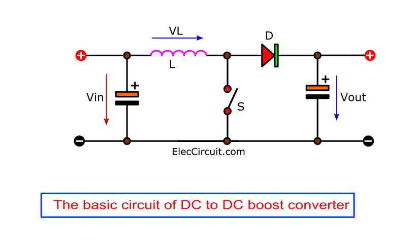
Boost Converters Dc To Dc Step Up Voltage Circuits Youtube A boost converter or step up converter is a dc to dc converter that increases voltage, while decreasing current, from its input to its output . it is a class of switched mode power supply (smps) containing at least two semiconductors, a diode and a transistor , and at least one energy storage element: a capacitor , inductor , or the two in. This electronics video tutorial provides a basic introduction into boost converters circuits that can step up the voltage of dc sources such as batteries a.

Boost Converter Basics Working Design Application The boost converter is a dc to dc converter designed to perform the step up conversion of applied dc input. in the boost converter, the supplied fixed dc input is boosted (or increased) to adjustable dc output voltage i.e. output voltage of the boost converter is always greater than the input voltage. so, a boost converter is also called a step. Boost converter design. in most any power supply schematic, the inputs are on the left and power flow is towards the load on the right. a boost is a little more than a backwards buck, though, so for a moment, let’s imagine that v in and v out in this schematic were reversed. now, it would change d1 and q1. the boost is a buck going backwards. High level circuit operating principle. a boost converter or step up converter aids in stepping up a dc voltage from the input to the output. the conduction state of the switch dictates the operation of the circuit. during the on state, the current flowing through the inductor increases linearly. the diode is not conducting. A look into how boost converters work in a very visual format. try this circuit: goo.gl nkhq9hboost converter wiki: en. .org wiki boos.

Diy Boost Converter How To Step Up Dc Voltage Efficiently Youtube High level circuit operating principle. a boost converter or step up converter aids in stepping up a dc voltage from the input to the output. the conduction state of the switch dictates the operation of the circuit. during the on state, the current flowing through the inductor increases linearly. the diode is not conducting. A look into how boost converters work in a very visual format. try this circuit: goo.gl nkhq9hboost converter wiki: en. .org wiki boos. June 14, 2024 by electrical4u. 💡. key learnings: boost converter definition: a boost converter (step up chopper) is a device that increases the input dc voltage to a higher output dc voltage. circuit components: the boost converter circuit includes an inductor, switch, diode, capacitor, and load, each playing a vital role in its operation. Boost converters are a type of dc dc switching converter that efficiently increase (step up) the input voltage to a higher output voltage. by storing energy in an inductor during the switch on phase and releasing it to the load during the switch off phase, this voltage conversion is made possible. power electronics applications requiring a.

Dc Dc Step Up Converter Schematic June 14, 2024 by electrical4u. 💡. key learnings: boost converter definition: a boost converter (step up chopper) is a device that increases the input dc voltage to a higher output dc voltage. circuit components: the boost converter circuit includes an inductor, switch, diode, capacitor, and load, each playing a vital role in its operation. Boost converters are a type of dc dc switching converter that efficiently increase (step up) the input voltage to a higher output voltage. by storing energy in an inductor during the switch on phase and releasing it to the load during the switch off phase, this voltage conversion is made possible. power electronics applications requiring a.

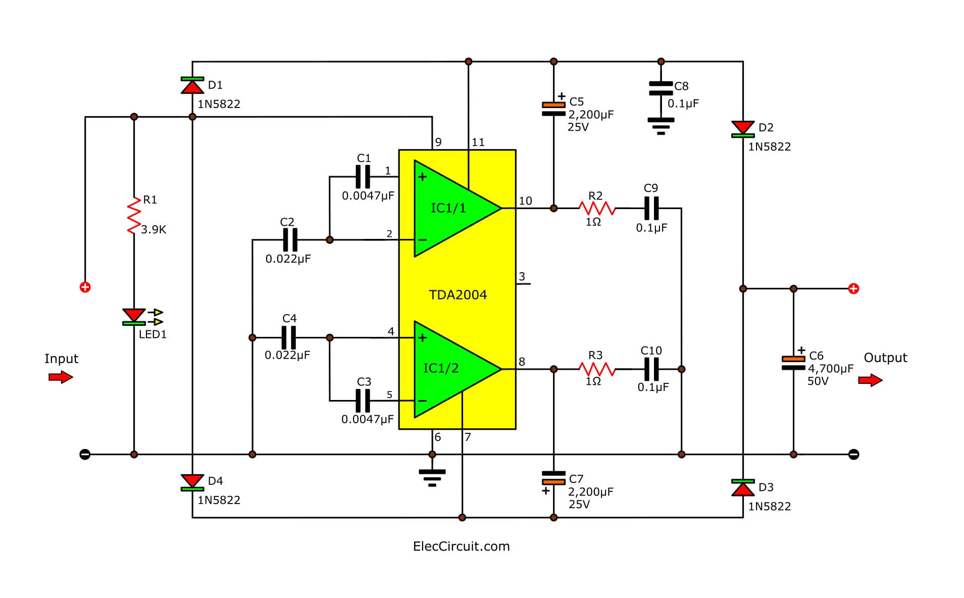
Draw Your Wiring Simple Dc To Dc Boost Up Circuit

Comments are closed.